4. To use the Headstock Spur (3) and |
|
|
| |
FIGURE C |
|
| TAILSTOCK | |
FACEPLATE | WOODSTOCK | HEADSTOCK HOLE | HOLE | |
(2) | (NOT INCLUDED) |
|
|
|
|
| PUSH OUT ROD |
|
|
|
| (22) |
|
|
|
| TAILSTOCK | |
FLAT HEAD | SPUR | ||
BRASS | (61) | ||
SCREWS | FIGURE E | ||
WOOD |
|
|
|
(83) |
|
|
|
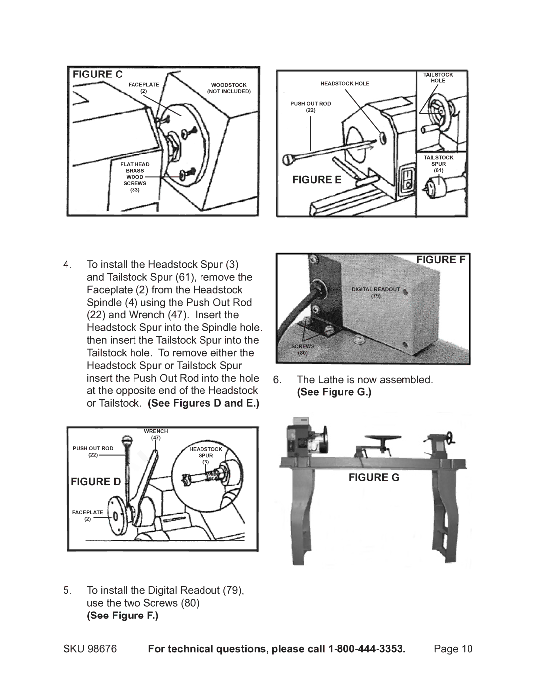
4. To install the Headstock Spur (3) | FIGURE F | |
| ||
and Tailstock Spur (61), remove the |
| |
Faceplate (2) from the Headstock | DIGITAL READOUT | |
Spindle (4) using the Push Out Rod | (79) | |
| ||
(22) and Wrench (47). Insert the |
| |
Headstock Spur into the Spindle hole. |
| |
then insert the Tailstock Spur into the | SCREWS | |
Tailstock hole. To remove either the | ||
(80) | ||
Headstock Spur or Tailstock Spur |
| |
insert the Push Out Rod into the hole 6. | The Lathe is now assembled. | |
at the opposite end of the Headstock | (See Figure G.) | |
or Tailstock. (See Figures D and E.) |
| |
WRENCH |
| |
(47) |
|
PUSH OUT ROD
(22)
HEADSTOCK
SPUR
(3)
FIGURE D
FIGURE G
FACEPLATE
(2)
5.To install the Digital Readout (79), use the two Screws (80).
(See Figure F.)
SKU 98676 | For technical questions, please call | Page 10 |