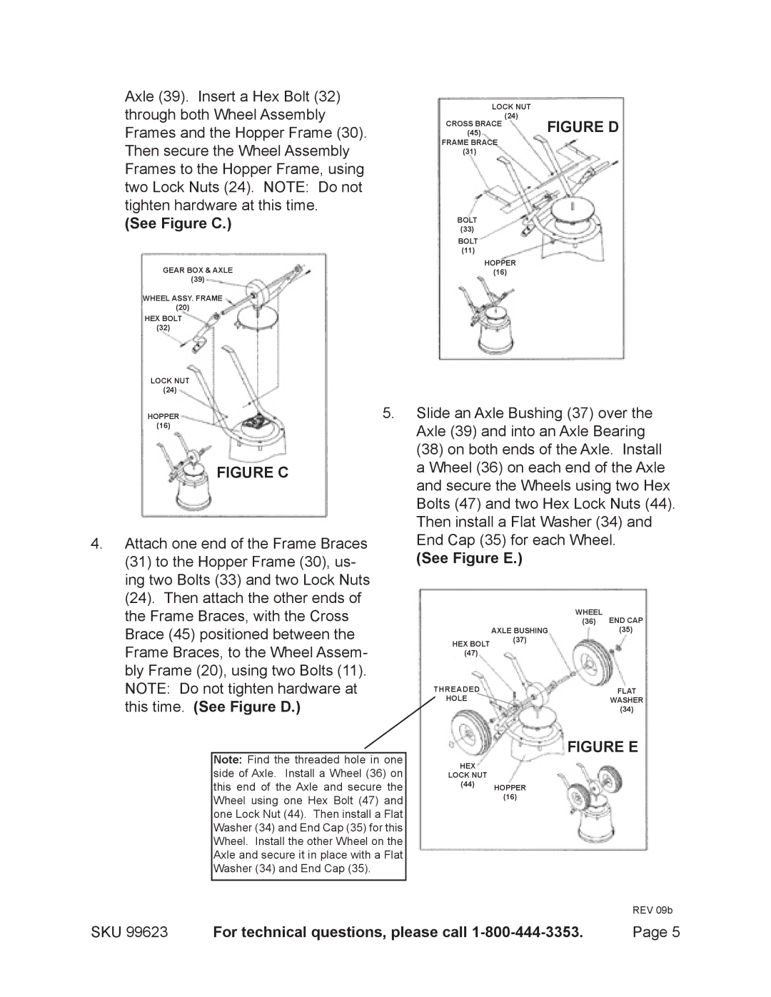
Axle (39). Insert a Hex Bolt (32) through both Wheel Assembly Frames and the Hopper Frame (30). Then secure the Wheel Assembly Frames to the Hopper Frame, using two Lock Nuts (24). NOTE: Do not tighten hardware at this time.
(See Figure C.)
GEAR BOX & AXLE
(39)
WHEEL ASSY. FRAME
(20)
HEX BOLT
(32)
LOCK NUT
(24)
HOPPER | 5. |
(16) |
|
FIGURE C
4.Attach one end of the Frame Braces
(31)to the Hopper Frame (30), us- ing two Bolts (33) and two Lock Nuts
(24).Then attach the other ends of the Frame Braces, with the Cross Brace (45) positioned between the Frame Braces, to the Wheel Assem- bly Frame (20), using two Bolts (11). NOTE: Do not tighten hardware at this time. (See Figure D.)
Note: Find the threaded hole in one side of Axle. Install a Wheel (36) on this end of the Axle and secure the Wheel using one Hex Bolt (47) and one Lock Nut (44). Then install a Flat Washer (34) and End Cap (35) for this Wheel. Install the other Wheel on the Axle and secure it in place with a Flat Washer (34) and End Cap (35).
LOCK NUT |
|
(24) | FIGURE D |
(45) | |
CROSS BRACE |
|
FRAME BRACE |
|
(31) |
|
BOLT
(33)
BOLT
(11)
HOPPER
(16)
Slide an Axle Bushing (37) over the Axle (39) and into an Axle Bearing
(38)on both ends of the Axle. Install a Wheel (36) on each end of the Axle and secure the Wheels using two Hex Bolts (47) and two Hex Lock Nuts (44). Then install a Flat Washer (34) and End Cap (35) for each Wheel.
(See Figure E.)
| WHEEL | END CAP |
| (36) | |
| AXLE BUSHING | (35) |
HEX BOLT | (37) |
|
|
| |
(47) |
|
|
THREADED |
| FLAT |
HOLE |
| WASHER |
|
| (34) |
FIGURE E
HEX
LOCK NUT
(44)HOPPER
(16)
REV 09b
SKU 99623 | For technical questions, please call | Page 5 |