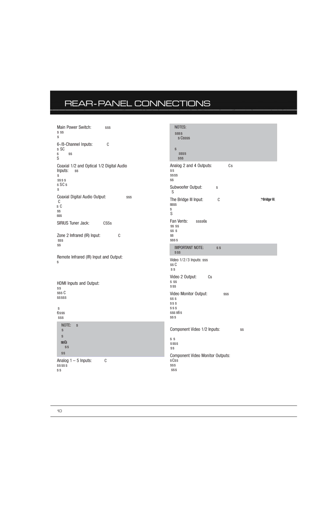
Main Power Switch: This mechanical switch turns the power supply on or off. It is usually left on, and cannot be turned on or off using the remote control.
6-/8-Channel Inputs: Connect the multichannel analog audio outputs of a non-HDMI player (DVD-Audio, SACD™, Blu-ray Disc™ or HD-DVD, or any other external decoder) to these jacks. See page 30 for more information.
Coaxial 1/2 and Optical 1/2 Digital Audio Inputs: If a source has a compatible digital audio output, and if you are not using an HDMI connection for audio for the device, connect it to one of these jacks to hear digital audio formats, such as Dolby Digital, DTS and linear PCM. Use only one type of digital audio connection for each source.
Coaxial Digital Audio Output: If a source is also an audio recorder, connect the Coaxial Digital Audio Output to the recorder’s matching input for improved recording quality. Only PCM digital audio signals are available for recording. Both coaxial and optical digital audio signals are available at this Digital Audio Output.
SIRIUS Tuner Jack: Connect a SIRIUS satellite radio tuner module here.
Zone 2 Infrared (IR) Input: Connect a remote IR receiver located in the remote zone of a multizone system to this jack to control the AVR (and any source devices connected to the Remote IR Output) from the remote zone.
Remote Infrared (IR) Input and Output: When the remote IR receiver on the front panel is blocked, connect an optional IR receiver to the Remote IR Input jack. The Remote IR Output may be connected to the Remote IR Input of a compatible product to enable remote control through the AVR.
HDMI Inputs and Output: HDMI (High-Definition Multimedia Interface) is a connection for transmitting digital audio and video signals between devices. Connect up to four HDMI- equipped source devices to the HDMI inputs using a single-cable connection.
When you connect the HDMI Output to your video display, the AVR 2600 will automatically transcode analog video signals to the HDMI format, upscaling to as high as 1080p.
NOTE: When connecting a DVI-equipped display to one of the HDMI Outputs:
•Use an HDMI-to-DVI adapter.
•Make sure the display is HDCP-compliant. If it isn’t, do not connect it to an HDMI Output; use an analog video connection instead.
•Always make a separate audio connection.
Analog 1 – 5 Inputs: Connect the left and right analog audio outputs of a source device to any of these inputs. These inputs may be paired with any video inputs.
NOTES:
•The Analog 2 and 4 inputs are each associated with a set of outputs. Consider using these connectors for an audio or video recorder.
•You may optionally connect a source to both an analog and digital audio input. This is useful for making recordings, for multizone applications or simply as a backup.
Analog 2 and 4 Outputs: Connect either of these analog audio outputs to the analog audio inputs of a recording device.
A signal is available at these outputs whenever an analog audio source is playing.
Subwoofer Output: If you have a powered subwoofer with a line-level input, connect it to the Subwoofer Output.
The Bridge III Input: Connect a Harman Kardon  docking station (not included) to this input for use with most docking iPod models, 4G and later, iPhone or iPhone 3G (not included). Turn the receiver off (Standby mode) when connecting The Bridge III.
Fan Vents: This area contains vents used by the AVR 2600’s fan to cool the system. Maintain a clearance of at least 3 inches from the nearest surface to avoid overheating the unit. It is normal for the fan to remain off at most normal volume levels. An automatic temperature sensor turns the fan on only when it is needed.
IMPORTANT NOTE: Never block the fan vents, as doing so could allow the AVR to overheat to dangerous levels.
Video 1/2/3 Inputs: Use these jacks to connect your video- capable source components (e.g., VCR, DVD player, cable TV box) to the receiver. Use only one type of video connection for each source.
Video 2 Output: Connect this analog video output to the composite video input of a recording device. A signal is available at this output whenever an analog video source is playing.
Video Monitor Output: If any of your sources use composite video connections, connect this monitor output to the corresponding input on your video display. If your video display is equipped with HDMI or component video inputs, this connection is unnecessary, as the AVR 2600 will convert the composite video source signal to the correct format for a single video-cable connection to the TV.
Component Video 1/2 Inputs: If a video source has analog component video (Y/Pb/Pr) capability, and if you are not using an HDMI connection, connect the component video outputs of the source to one of the sets of component video inputs. Do not make any other video connections to that source.
Component Video Monitor Outputs: If you are using one of the Component Video Inputs and your television or video display is component-video-capable (but does not have an HDMI input), connect these jacks to the video display.