REAR-PANEL CONNECTIONS
32 k i g e | c a ° fl | › |
33 31 j h f | d b · ‡ | fi |
¡
™
£ |
¢ |
∞ |
SURRSURR
, 1A ![]()
![]()
|
|
|
| , 0.5A |
|
§ | ¶ | • ª ‚ ⁄ | ¤ | ‹ |
|
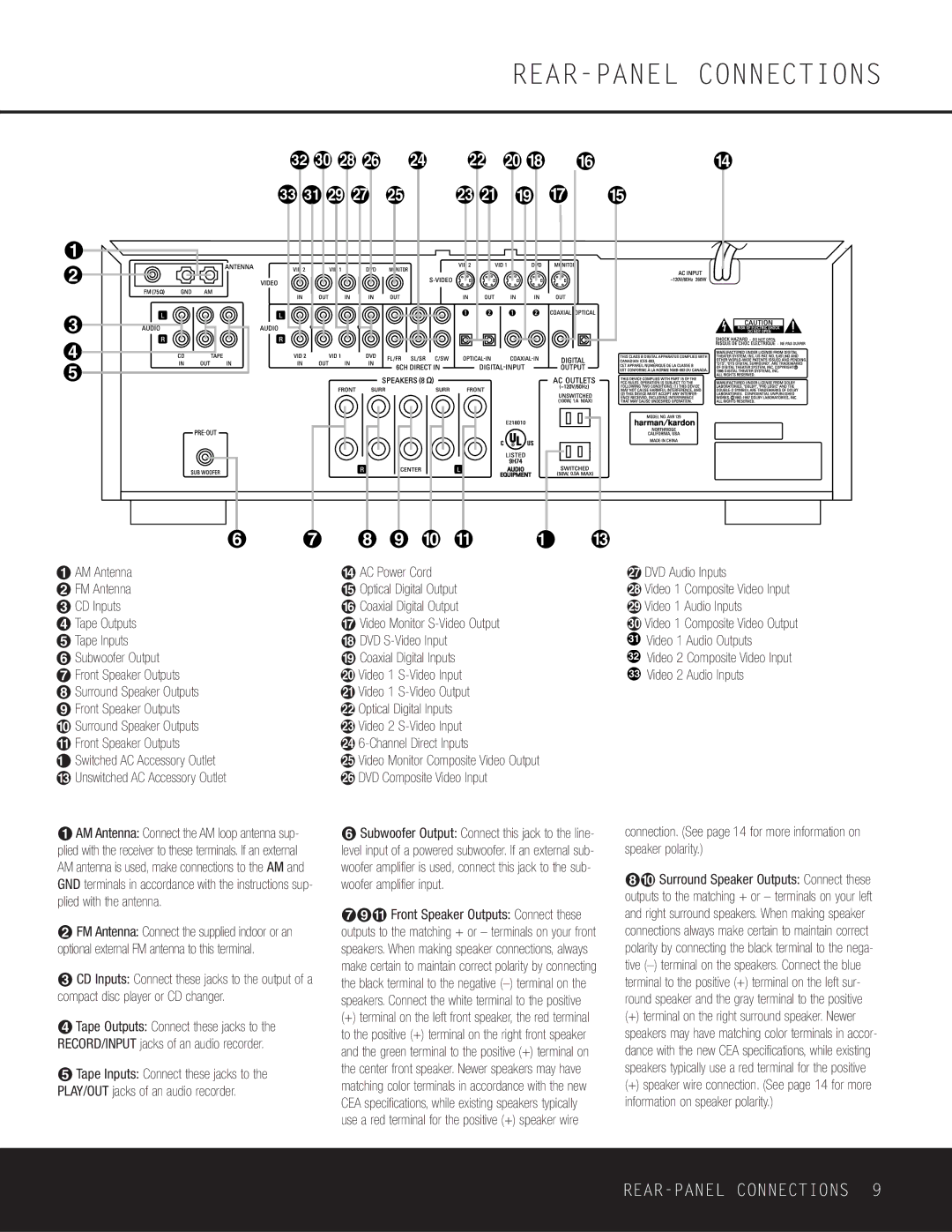
¡ AM Antenna |
| › AC Power Cord |
| h DVD Audio Inputs | |
™ FM Antenna |
| fi Optical Digital Output |
| i Video 1 Composite Video Input | |
£ CD Inputs |
| fl Coaxial Digital Output |
| j Video 1 Audio Inputs | |
¢ Tape Outputs |
| ‡ Video Monitor |
| k Video 1 Composite Video Output | |
∞ Tape Inputs |
| ° DVD |
| 31 | Video 1 Audio Outputs |
§ Subwoofer Output |
| · Coaxial Digital Inputs |
| 32 | Video 2 Composite Video Input |
¶ Front Speaker Outputs |
| a Video 1 |
| 33 | Video 2 Audio Inputs |
• Surround Speaker Outputs |
| b Video 1 |
|
|
|
ª Front Speaker Outputs |
| c Optical Digital Inputs |
|
|
|
‚ Surround Speaker Outputs |
| d Video 2 |
|
|
|
⁄ Front Speaker Outputs |
| e |
|
|
|
¤ Switched AC Accessory Outlet |
| f Video Monitor Composite Video Output |
|
| |
‹ Unswitched AC Accessory Outlet |
| g DVD Composite Video Input |
|
|
|
¡AM Antenna: Connect the AM loop antenna sup- plied with the receiver to these terminals. If an external AM antenna is used, make connections to the AM and GND terminals in accordance with the instructions sup- plied with the antenna.
™FM Antenna: Connect the supplied indoor or an optional external FM antenna to this terminal.
£CD Inputs: Connect these jacks to the output of a compact disc player or CD changer.
¢Tape Outputs: Connect these jacks to the RECORD/INPUT jacks of an audio recorder.
∞Tape Inputs: Connect these jacks to the PLAY/OUT jacks of an audio recorder.
§Subwoofer Output: Connect this jack to the line- level input of a powered subwoofer. If an external sub- woofer amplifier is used, connect this jack to the sub- woofer amplifier input.
¶ª⁄ Front Speaker Outputs: Connect these outputs to the matching + or – terminals on your front speakers. When making speaker connections, always make certain to maintain correct polarity by connecting the black terminal to the negative
(+)terminal on the left front speaker, the red terminal to the positive (+) terminal on the right front speaker and the green terminal to the positive (+) terminal on the center front speaker. Newer speakers may have matching color terminals in accordance with the new CEA specifications, while existing speakers typically use a red terminal for the positive (+) speaker wire
connection. (See page 14 for more information on speaker polarity.)
•‚ Surround Speaker Outputs: Connect these outputs to the matching + or – terminals on your left and right surround speakers. When making speaker connections always make certain to maintain correct polarity by connecting the black terminal to the nega- tive
(+)terminal on the right surround speaker. Newer speakers may have matching color terminals in accor- dance with the new CEA specifications, while existing speakers typically use a red terminal for the positive
(+)speaker wire connection. (See page 14 for more information on speaker polarity.)