INSTALLATION AND CONNECTIONS
System Installation
After unpacking the unit, and placing it on a solid surface capable of supporting its weight, you will need to make the connections to your audio and video equipment.
Audio Equipment Connections
We recommend that you use
When making connections to audio source equipment or speakers it is always a good practice to unplug the unit from the AC wall outlet. This prevents any possibil- ity of accidentally sending audio or transient signals to the speakers that may damage them.
1.Connect the analog output of a CD player to the CD Inputs £.
NOTE: When the CD player has both fixed and vari- able audio outputs it is best to use the fixed output unless you find that the input to the receiver is so low that the sound is noisy, or so high that the signal is distorted.
2.Connect the analog Play/Out jacks of a cassette deck, MD,
3.Connect the output of any digital sources to the appropriate input connections on the AVR 125 rear panel. Note that the Optical and Coaxial Digital Inputs ·c#$ may be used with a Dolby Digital or DTS source such as a DVD player, or the output of a conventional CD or LD player’s PCM
4.Connect the Optical Digital Output fi or Coaxial Digital Output fl on the rear panel of the AVR 125 to the matching digital input connections on a
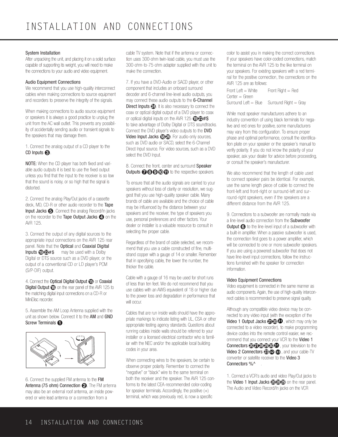
5.Assemble the AM Loop Antenna supplied with the unit as shown below. Connect it to the AM and GND Screw Terminals ¡.
6.Connect the supplied FM antenna to the FM Antenna (75 ohm) Connection ™. The FM antenna may also be an external roof antenna, an inside pow- ered or wire lead antenna or a connection from a
cable TV system. Note that if the antenna or connec- tion uses
7.If you have a
8.Connect the front, center and surround Speaker Outputs ¶•ª‚⁄ to the respective speakers.
To ensure that all the audio signals are carried to your speakers without loss of clarity or resolution, we sug- gest that you use
Regardless of the brand of cable selected, we recom- mend that you use a cable constructed of fine, multi- strand copper with a gauge of 14 or smaller. Remember that in specifying cable, the lower the number, the thicker the cable.
Cable with a gauge of 16 may be used for short runs of less than ten feet. We do not recommend that you use cables with an AWG equivalent of 18 or higher due to the power loss and degradation in performance that will occur.
Cables that are run inside walls should have the appro- priate markings to indicate listing with UL, CSA or other appropriate testing agency standards. Questions about running cables inside walls should be referred to your installer or a licensed electrical contractor who is famil- iar with the NEC and/or the applicable local building codes in your area.
When connecting wires to the speakers, be certain to observe proper polarity. Remember to connect the “negative” or “black” wire to the same terminal on both the receiver and the speaker. The AVR 125 con- forms to the latest
color to assist you in making the correct connections. If your speakers have
Front Left = White | Front Right = Red |
Center = Green |
|
Surround Left = Blue | Surround Right = Gray |
While most speaker manufacturers adhere to an industry convention of using black terminals for nega- tive and red ones for positive, some manufacturers may vary from this configuration. To ensure proper phase and optimal performance, consult the identifica- tion plate on your speaker or the speaker’s manual to verify polarity. If you do not know the polarity of your speaker, ask your dealer for advice before proceeding, or consult the speaker’s manufacturer.
We also recommend that the length of cable used to connect speaker pairs be identical. For example, use the same length piece of cable to connect the
9.Connections to a subwoofer are normally made via a
Video Equipment Connections
Video equipment is connected in the same manner as audio components. Again, the use of
Although any compatible video device may be con- nected to any video input (with the exception of the Video 1 Output Jacks bk31 , which may only be connected to a video recorder), to make programming device codes into the remote control easier, we rec- ommend that you connect your VCR to the Video 1 Connectors abijk31 , your television to the Video 2 Connectors d32 33 , and your
1.Connect a VCR’s audio and video Play/Out jacks to the Video 1 Input Jacks aij on the rear panel. The Audio and Video Record/In jacks on the VCR
14 INSTALLATION AND CONNECTIONS