| Installation | |
|
| Outside Air |
|
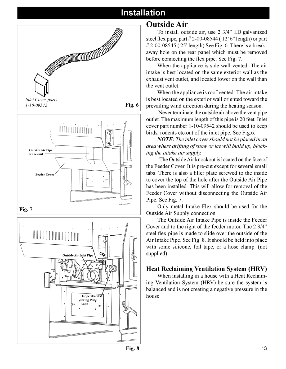
| To install outside air, use 2 3/4” I.D.galvanized |
|
| steel flex pipe, part # |
|
| # |
|
| away hole on the rear panel which must be removed |
|
| before connecting the flex pipe. See Fig. 7. |
|
| When the appliance is side wall vented: The air |
|
| intake is best located on the same exterior wall as the |
|
| exhaust vent outlet, and located lower on the wall than |
|
| the vent outlet. |
|
| When the appliance is roof vented: The air intake |
Inlet Cover part# | Fig. 6 | is best located on the exterior wall oriented toward the |
prevailing wind direction during the heating season. | ||
|
| Never terminate the outside air above the vent pipe |
|
| outlet. The maximum length of this pipe is 20 feet. Inlet |
|
| cover part number |
|
| birds, rodents etc.out of the inlet pipe. See Fig.6. |
|
| NOTE: The inlet cover should not be placed in an |
Outside Air Pipe |
| area where drifting of snow or ice will build up, block- |
| ing the intake air supply. | |
Knockout |
| |
|
| The Outside Air knockout is located on the face of |
|
| the Feeder Cover. It is |
Feeder Cover |
| tabs. There is also a filler plate screwed to the inside |
|
| to cover the top of the hole after the Outside Air Pipe |
|
| has been installed. This will allow for removal of the |
|
| Feeder Cover without disconnecting the Outside Air |
|
| Pipe. See Fig. 7. |
Fig. 7 |
| Only metal Intake Flex should be used for the |
| Outside Air Supply connection. | |
|
| |
|
| The Outside Air Intake Pipe is inside the Feeder |
|
| Cover and to the right of the feeder motor. The 2 3/4” |
|
| steel flex pipe is made to slide over the outside of the |
|
| Air Intake Pipe. See Fig. 8. It should be held into place |
|
| with some silicone, foil tape, or a hose clamp. (not |
Outside Air Inlet Pipe |
| supplied) |
| Heat Reclaiming Ventilation System (HRV) |
| When installing in a house with a Heat Reclaim- |
| ing Ventilation System (HRV) be sure the system is |
| balanced and is not creating a negative pressure in the |
Hopper/Feeder | house. |
Swing Plate |
|
Knob |
|
Fig. 8 | 13 |
