Installation
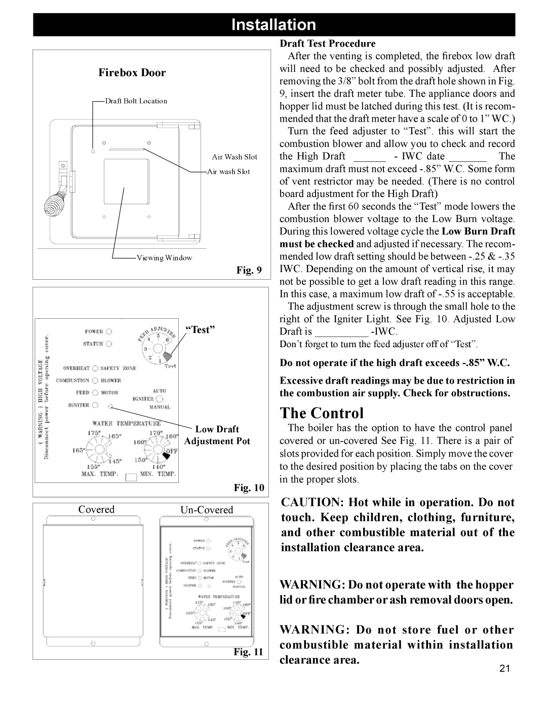
Firebox Door |
Draft Bolt Location |
Air Wash Slot |
Air wash Slot |
Viewing Window |
Fig. 9 |
“Test” |
![]() Low Draft
Low Draft
Adjustment Pot
Fig. 10
CoveredUn-Covered
Fig. 11
Draft Test Procedure
After the venting is completed, the firebox low draft will need to be checked and possibly adjusted. After removing the 3/8” bolt from the draft hole shown in Fig. 9, insert the draft meter tube. The appliance doors and hopper lid must be latched during this test. (It is recom- mended that the draft meter have a scale of 0 to 1” WC.)
Turn the feed adjuster to “Test”. this will start the combustion blower and allow you to check and record the High Draft ______ - IWC date _______ The
maximum draft must not exceed
After the first 60 seconds the “Test” mode lowers the combustion blower voltage to the Low Burn voltage. During this lowered voltage cycle the Low Burn Draft must be checked and adjusted if necessary. The recom- mended low draft setting should be between
The adjustment screw is through the small hole to the right of the Igniter Light. See Fig. 10. Adjusted Low Draft is __________
Don’t forget to turn the feed adjuster off of “Test”.
Do not operate if the high draft exceeds
Excessive draft readings may be due to restriction in the combustion air supply. Check for obstructions.
The Control
The boiler has the option to have the control panel covered or
CAUTION: Hot while in operation. Do not touch. Keep children, clothing, furniture, and other combustible material out of the installation clearance area.
WARNING: Do not operate with the hopper lid or fire chamber or ash removal doors open.
WARNING: Do not store fuel or other combustible material within installation clearance area.
21