Over Heat Safety Zone
OverHeat Safety Zone (Dump Zone): STRONGLY RECOMMENDED in all installations.
When the pellet boiler is operating at High burn, and all demand from the heating system stops, the control will reduce the feed rate and shut down completely as necessary. This may take several minutes, and the remain- ing heat may cause the water temperature to continue to rise. If the temperature gets too high, the OVERHEAT SAFETY ZONE light on the control (see page 23) will illuminate, and the DARK BLUE circuit in the junction box is energized(see wiring diagram). This circuit will flow 120V to operate a circulator pump installed to flow to the overheat dump zone established in the original installation plan. If opening a zone valve is the chosen method of dumping the excess heat, a voltage reduction relay will most likely be needed. If the water temperature continues to rise to the risk of boiling point, the feed system will stop and the boiler will
The boiling temperature of water varies at different altitudes and atmospheric pressures. Therefore, at eleva- tions above 3000 feet, and when using the atmospheric conversion, circuit board dipswitch #6 must be in the “ON” position.
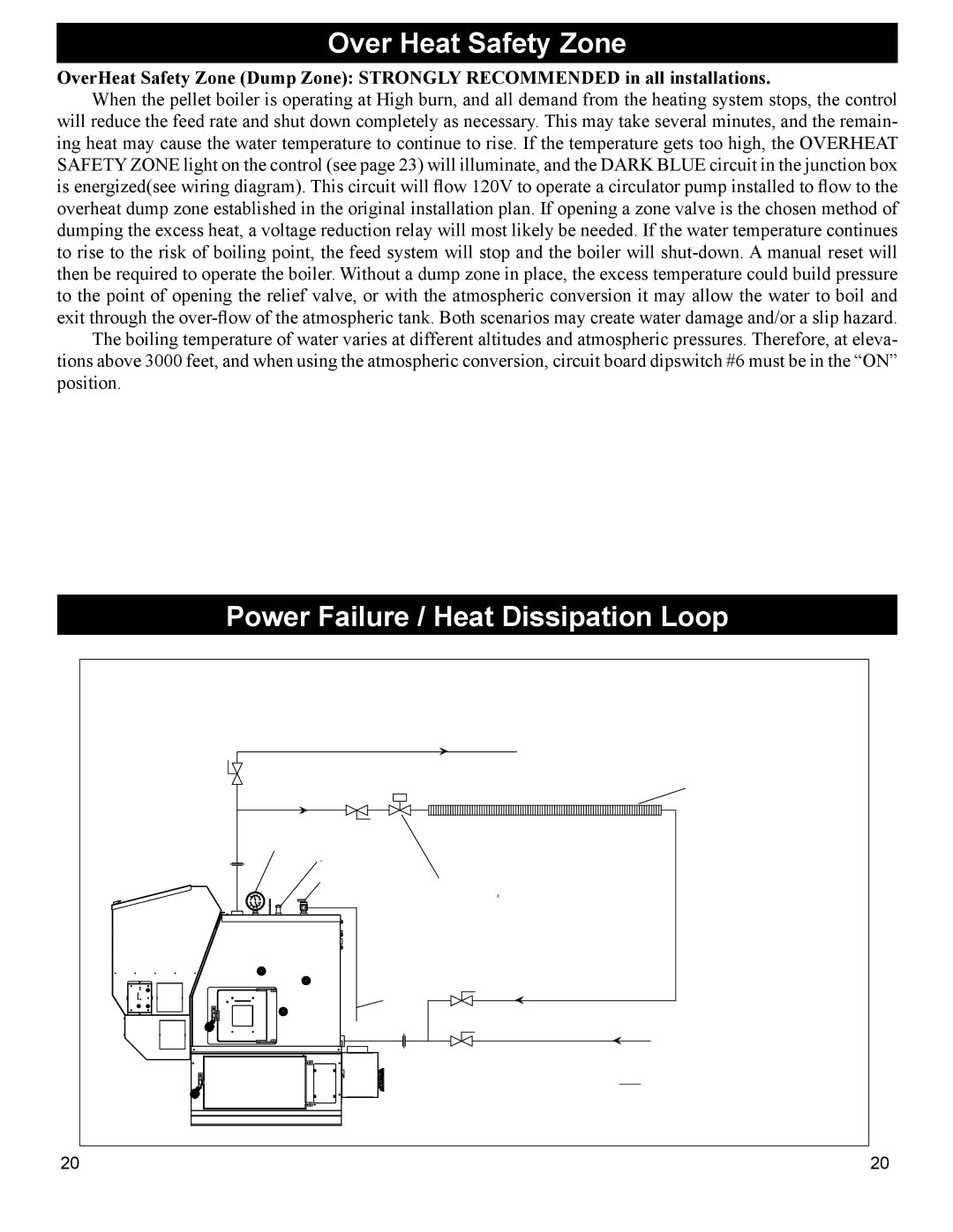
Power Failure / Heat Dissipation Loop
EXAMPLE OF PIPING IN ACCORDANCE
WITH
A POWER FAILURE HEAT DISSIPATION LOOP
BALANCING |
| SYSTEM SUPPLY | ||
VALVE |
|
|
|
|
|
|
|
|
|
UNION
POWER FAILURE SYSTEM SUPPLY 3/4"
*TEMPERATURE/PRESSURE GAUGE
*AQUASTAT WELL
*PRESSURE RELIEF VALVE
PIPE TO WITHIN 6" OF THE FLOOR OR A FLOOR DRAIN
UNION
|
|
|
|
|
|
|
|
|
|
|
|
|
|
|
|
|
|
|
|
|
|
|
|
|
|
|
|
|
|
|
|
|
|
|
|
|
|
|
|
|
|
|
|
|
|
|
|
|
|
|
|
|
|
|
|
|
|
|
|
|
|
|
|
|
|
|
|
|
|
|
|
|
|
|
|
|
|
|
|
|
|
|
|
|
|
|
|
|
|
|
|
|
|
|
|
|
| MINIMUM OF 72" OF 3/4" |
|
|
|
|
|
|
|
|
|
|
|
|
|
|
| (HIGH TEMPERATURE) BASEBOARD HEAT |
|
|
|
|
|
|
|
|
|
|
|
|
|
|
|
|
|
|
|
|
|
|
|
|
|
|
|
|
|
|
|
|
|
|
|
|
| FINNED BASEBOARD | |||||||||||||||||||||||||||||||||||||||||||||
|
|
|
|
|
|
|
|
|
|
|
|
|
|
|
|
|
|
|
|
|
|
|
|
|
|
|
|
|
|
|
|
|
|
|
|
|
|
|
|
|
|
|
|
|
|
|
|
|
|
|
|
|
|
|
|
|
|
|
|
|
|
|
|
|
|
|
|
|
|
|
|
|
|
|
|
|
|
|
|
|
|
|
|
|
|
|
|
|
|
|
|
|
|
|
|
|
| BASEBOARD MUST BE AT LEAST |
|
|
|
|
|
|
|
|
|
|
|
|
|
|
|
|
|
|
|
|
|
|
|
|
|
|
|
|
|
|
|
|
|
|
|
|
|
|
|
|
|
|
|
|
|
|
|
|
|
|
|
|
|
|
|
|
|
|
|
|
|
|
|
|
|
|
|
|
|
|
|
|
|
|
|
|
|
|
|
|
|
|
|
|
|
|
|
|
|
|
|
|
|
|
|
|
|
| 24" HIGHER THAN BOILER FOR |
|
|
|
|
|
|
|
|
|
|
|
|
|
|
|
|
|
|
|
|
|
|
|
|
|
|
|
|
|
|
|
|
|
|
|
|
|
|
|
|
|
|
|
|
|
|
|
|
|
|
|
|
|
|
|
|
|
|
|
|
|
|
|
|
|
|
|
|
|
|
|
|
|
|
|
|
|
|
|
|
|
|
|
|
|
|
|
|
|
|
|
|
|
|
|
|
|
| PROPER GRAVITY FLOW |
120VAC,NORMALLY OPEN,FULL FLOW, SOLENOID VALVE or EQUIVALENT
THE SOLENOID SHOULD BE POWERED BY THE SAME CIRCUIT AS THE BOILER
POWER FAILURE SYSTEM RETURN 3/4"
|
|
|
|
SYSTEM RETURN | |||
| |||
| NOTE: ALWAYS REFER TO THE INDIVIDUAL COMPONENTS |
| RECOMMENDED INSTALLATION INSTRUCTIONS FOR THE PROPER |
* ITEMS SUPPLIED | MOUNTING POSITION AND LOCATION WITHIN THE PIPING SYSTEM. |
20 | 20 |