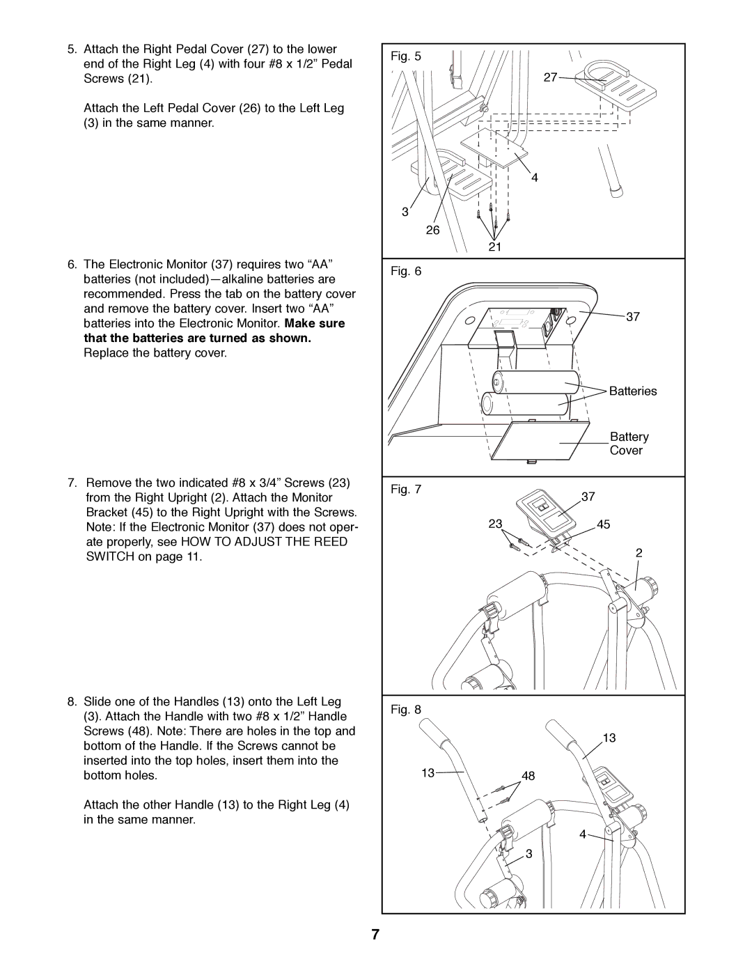
5. Attach the Right Pedal Cover (27) to the lower | Fig. 5 |
| |
end of the Right Leg (4) with four #8 x 1/2Ó Pedal |
| ||
| 27 | ||
Screws (21). |
| ||
Attach the Left Pedal Cover (26) to the Left Leg |
|
| |
(3) in the same manner. |
|
| |
|
| 4 | |
| 3 |
| |
| 26 |
| |
| 21 |
| |
6. The Electronic Monitor (37) requires two ÒAAÓ | Fig. 6 |
| |
batteries (not included)Ñalkaline batteries are |
| ||
|
| ||
recommended. Press the tab on the battery cover |
|
| |
and remove the battery cover. Insert two ÒAAÓ |
| 37 | |
batteries into the Electronic Monitor. Make sure |
| ||
|
| ||
that the batteries are turned as shown. |
|
| |
Replace the battery cover. |
|
| |
|
| Batteries | |
|
| Battery | |
|
| Cover | |
7. Remove the two indicated #8 x 3/4Ó Screws (23) | Fig. 7 | 37 | |
from the Right Upright (2). Attach the Monitor | |||
| |||
Bracket (45) to the Right Upright with the Screws. | 23 | 45 | |
Note: If the Electronic Monitor (37) does not oper- | |||
ate properly, see HOW TO ADJUST THE REED |
| 2 | |
SWITCH on page 11. |
| ||
|
| ||
8. Slide one of the Handles (13) onto the Left Leg | Fig. 8 |
| |
(3). Attach the Handle with two #8 x 1/2Ó Handle |
| ||
|
| ||
Screws (48). Note: There are holes in the top and |
| 13 | |
bottom of the Handle. If the Screws cannot be |
| ||
|
| ||
inserted into the top holes, insert them into the | 13 |
| |
bottom holes. | 48 | ||
Attach the other Handle (13) to the Right Leg (4) |
|
| |
in the same manner. |
|
| |
|
| 4 | |
|
| 3 | |
| 7 |
|