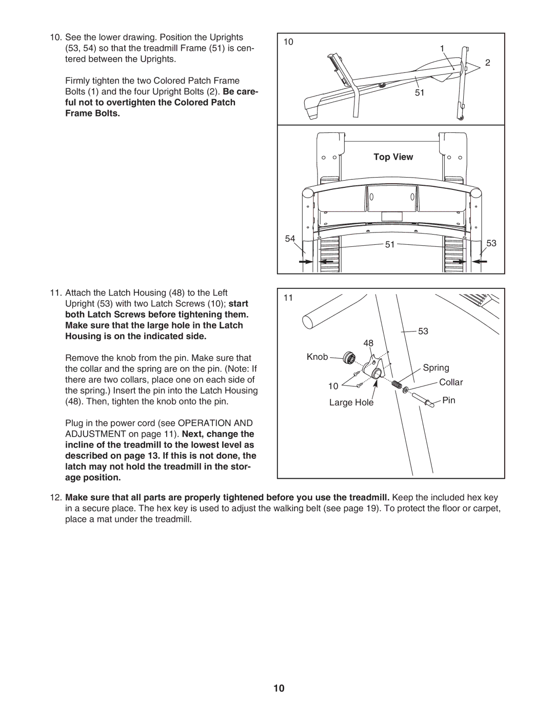
10.See the lower drawing. Position the Uprights (53, 54) so that the treadmill Frame (51) is cen- tered between the Uprights.
Firmly tighten the two Colored Patch Frame Bolts (1) and the four Upright Bolts (2). Be care- ful not to overtighten the Colored Patch Frame Bolts.
11.Attach the Latch Housing (48) to the Left Upright (53) with two Latch Screws (10); start both Latch Screws before tightening them. Make sure that the large hole in the Latch Housing is on the indicated side.
Remove the knob from the pin. Make sure that the collar and the spring are on the pin. (Note: If there are two collars, place one on each side of the spring.) Insert the pin into the Latch Housing (48). Then, tighten the knob onto the pin.
Plug in the power cord (see OPERATION AND ADJUSTMENT on page 11). Next, change the incline of the treadmill to the lowest level as described on page 13. If this is not done, the latch may not hold the treadmill in the stor- age position.
10 |
| 1 |
|
| |
|
| 2 |
|
| 51 |
| Top View |
|
54 | 51 | 53 |
| ||
11 |
|
|
|
| 53 |
| 48 |
|
| Knob |
|
|
| Spring |
| 10 | Collar |
|
| |
| Large Hole | Pin |
12.Make sure that all parts are properly tightened before you use the treadmill. Keep the included hex key in a secure place. The hex key is used to adjust the walking belt (see page 19). To protect the floor or carpet, place a mat under the treadmill.
10