98 | 1 | iFIT Wire | 113 | 1 | Edge Guard |
99 | 1 | Upright Grommet | 114 | 2 | Upright Endcap |
100 | 1 | Allen Wrench | 115 | 2 | Metal Plate |
101 | 10 | 3/4” Tek Screw | 116 | 2 | Belly Pan Interface |
102 | 2 | Handrail Endcap | 117 | 2 | Rear Foot Spacer |
103 | 1 | Power Board Plate | # | 1 | Pulse Plate Cover |
104 | 4 | Base Cap | # | 1 | 8” Blue Wire, 2F |
105 | 1 | Controller Wire | # | 1 | 4” Blue Wire, 2F |
106 | 1 | Choke | # | 1 | 8” White Wire, 2F |
107 | 1 | Silver Screw | # | 1 | 4” White Wire, M/F |
108 | 1 | Static Decal | # | 1 | 8” Green Wire, 2 Ring |
109 | 2 | Lift Spacer | # | 1 | User's Manual |
110 | 1 | Connector Cover |
|
|
|
111 | 1 | Hood Spacer | # These parts are not illustrated. | ||
112 | 2 | Bumper | Specifications are subject to change without notice. | ||
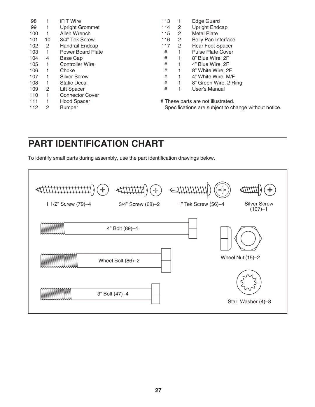
PART IDENTIFICATION CHART
To identify small parts during assembly, use the part identification drawings below.
1 1/2” Screw | 3/4” Screw | 1” Tek Screw | Silver Screw |
|
|
| |
| 4” Bolt |
|
|
| Wheel Bolt | Wheel Nut | |
|
|
| |
| 3” Bolt |
|
|
|
| Star | Washer |
27