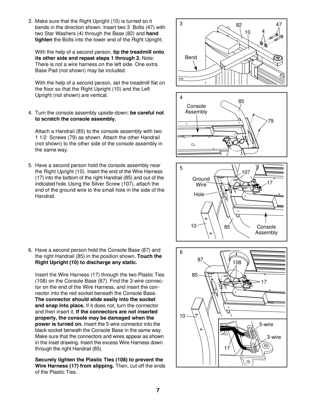
3.Make sure that the Right Upright (10) is turned so it bends in the direction shown. Insert two 3” Bolts (47) with two Star Washers (4) through the Base (82) and hand tighten the Bolts into the lower end of the Right Upright.
With the help of a second person, tip the treadmill onto its other side and repeat steps 1 through 3. Note: There is not a wire harness on the left side. One extra Base Pad (not shown) may be included.
With the help of a second person, set the treadmill flat on the floor so that the Right Upright (10) and the Left Upright (not shown) are vertical.
4.Turn the console assembly
Attach a Handrail (85) to the console assembly with two 1 1/2” Screws (79) as shown. Attach the other Handrail (not shown) to the other side of the console assembly in the same way.
3 | 82 | 47 |
| 10 | 4 |
| Bend |
|
4 | 85 |
|
|
| |
| Console |
|
| Assembly |
|
|
| 79 |
5.Have a second person hold the console assembly near the Right Upright (10). Insert the end of the Wire Harness (17) into the bottom of the right Handrail (85) and out of the indicated hole. Using the Silver Screw (107), attach the end of the ground wire to the small hole in the side of the Handrail.
6.Have a second person hold the Console Base (87) and the right Handrail (85) in the position shown. Touch the
Right Upright (10) to discharge any static.
Insert the Wire Harness (17) through the two Plastic Ties (108) on the Console Base (87). Find the
The connector should slide easily into the socket and snap into place. If it does not, turn the connector and then insert it. If the connectors are not inserted properly, the console may be damaged when the power is turned on. Insert the
Securely tighten the Plastic Ties (108) to prevent the Wire Harness (17) from slipping. Then, cut off the ends of the Plastic Ties.
7
5 |
| 107 |
|
| |
Ground |
| 17 |
Wire |
| |
|
| |
Hole |
|
|
10 | 85 | Console |
|
| Assembly |
6 |
|
|
87 |
| 108 |
|
| |
85 |
|
|
|
| 17 |
10 |
|
|
|
| |
|
| |
| 17 |
|