R
ZERO CLEARANCE ADJUSTABLE TRIM SUPPORT
Two sizes: 9”d x 45”w and 12”d x 50”w, both 2” to10” Height Adjustment
Included in Kit: (1) Trim Top, (1) Trim Front, (2) Trim Sides,
Tools Needed: Phillips Head Screwdriver, Sheet Metal Shears, Measuring Tape, Gloves
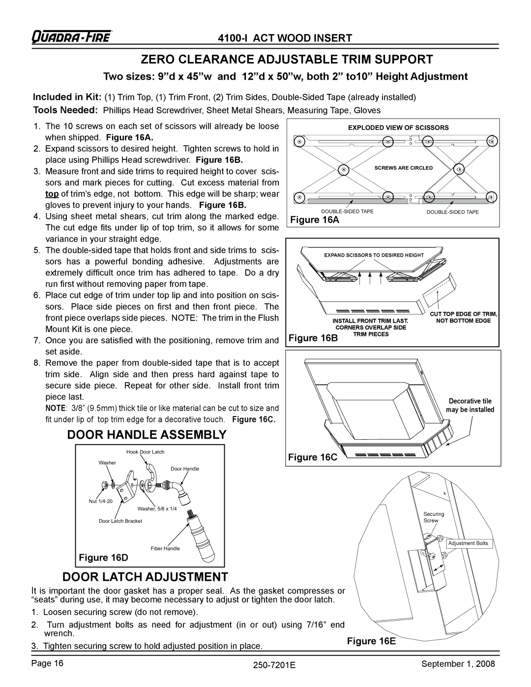
1.The 10 screws on each set of scissors will already be loose when shipped. Figure 16A.
2.Expand scissors to desired height. Tighten screws to hold in place using Phillips Head screwdriver. Figure 16B.
3.Measure front and side trims to required height to cover scis- sors and mark pieces for cutting. Cut excess material from top of trim’s edge, not bottom. This edge will be sharp; wear gloves to prevent injury to your hands. Figure 16B.
4.Using sheet metal shears, cut trim along the marked edge. The cut edge fits under lip of top trim, so it allows for some variance in your straight edge.
5.The
6.Place cut edge of trim under top lip and into position on scis- sors. Place side pieces on first and then front piece. The front piece overlaps side pieces. NOTE: The trim in the Flush
Mount Kit is one piece.
7.Once you are satisfied with the positioning, remove trim and set aside.
8.Remove the paper from
NOTE: 3/8” (9.5mm) thick tile or like material can be cut to size and fit under lip of top trim edge for a decorative touch. Figure 16C.
DOOR HANDLE ASSEMBLY
Hook Door Latch
Washer
Door Handle
Nut
Washer, 5/8 x 1/4
Door Latch Bracket
Fiber Handle
Figure 16D
EXPLODED VIEW OF SCISSORS | |
| SCREWS ARE CIRCLED |
Figure 16A |
|
EXpAND SCISSORS TO DESIRED HEIGHT
| CUT TOp EDGE OF TRIM, |
INSTALL FRONT TRIM LAST. | NOT BOTTOM EDGE |
CORNERS OVERLAp SIDE
Figure 16B | TRIM pIECES |
|
Decorative tile |
may be installed |
Figure 16C |
Securing
Screw
Adjustment Bolts
| DOOR LATCH ADJUSTMENT |
|
| |
It is important the door gasket has a proper seal. As the gasket compresses or |
| |||
“seats” during use, it may become necessary to adjust or tighten the door latch. |
| |||
1. | Loosen securing screw (do not remove). |
|
| |
2. | Turn adjustment bolts as need for adjustment (in or out) using 7/16” end |
| ||
| wrench. |
| Figure 16E | |
3. | Tighten securing screw to hold adjusted position in place. | |||
| ||||
|
|
|
| |
Page 16 | September 1, 2008 | |||