D. How to Use the Vent Graph | E. Venting Guidelines |
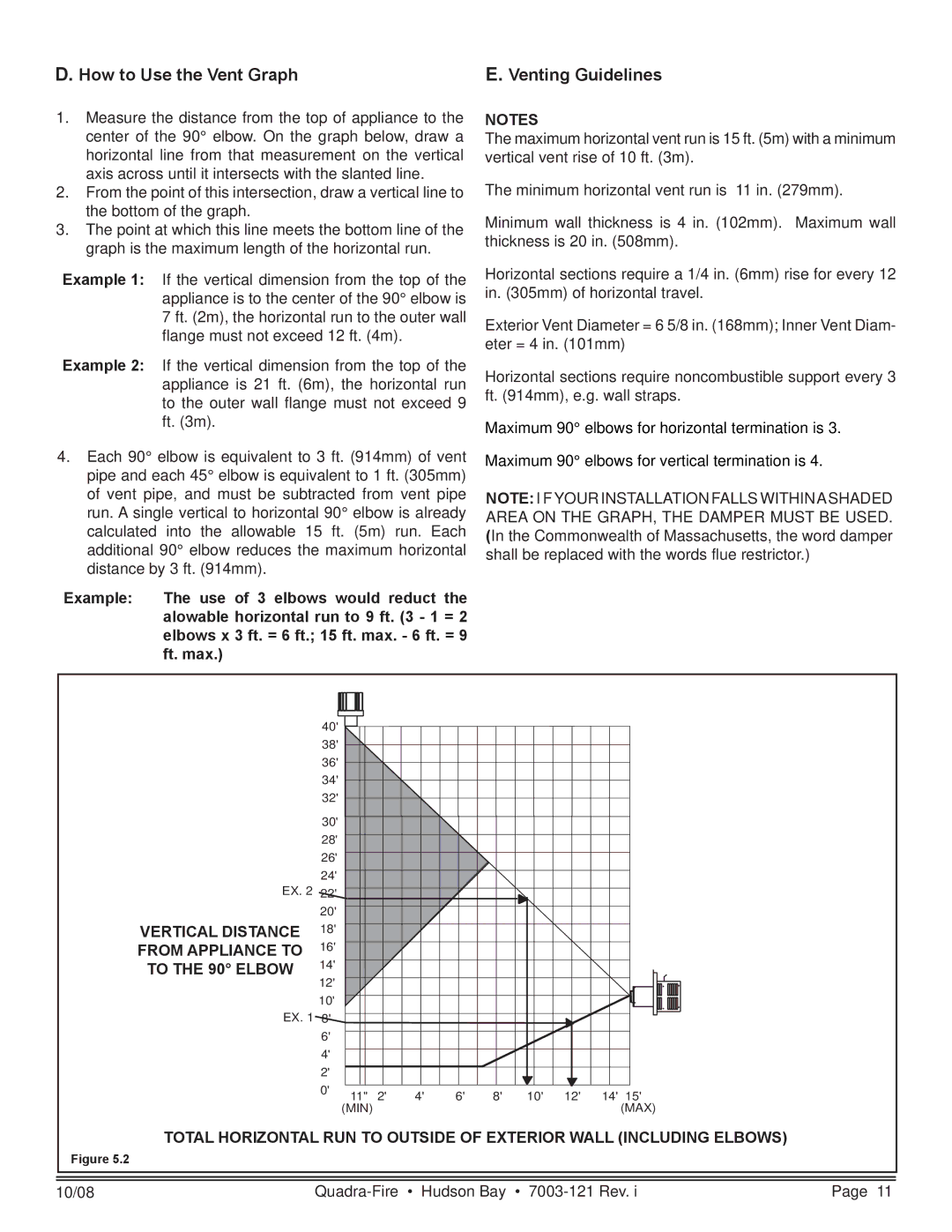
1.Measure the distance from the top of appliance to the center of the 90° elbow. On the graph below, draw a horizontal line from that measurement on the vertical axis across until it intersects with the slanted line.
2.From the point of this intersection, draw a vertical line to the bottom of the graph.
3.The point at which this line meets the bottom line of the graph is the maximum length of the horizontal run.
Example 1: If the vertical dimension from the top of the appliance is to the center of the 90° elbow is 7 ft. (2m), the horizontal run to the outer wall flange must not exceed 12 ft. (4m).
Example 2: If the vertical dimension from the top of the appliance is 21 ft. (6m), the horizontal run to the outer wall flange must not exceed 9 ft. (3m).
4.Each 90° elbow is equivalent to 3 ft. (914mm) of vent pipe and each 45° elbow is equivalent to 1 ft. (305mm) of vent pipe, and must be subtracted from vent pipe run. A single vertical to horizontal 90° elbow is already calculated into the allowable 15 ft. (5m) run. Each additional 90° elbow reduces the maximum horizontal distance by 3 ft. (914mm).
Example: The use of 3 elbows would reduct the alowable horizontal run to 9 ft. (3 - 1 = 2 elbows x 3 ft. = 6 ft.; 15 ft. max. - 6 ft. = 9 ft. max.)
NOTES
The maximum horizontal vent run is 15 ft. (5m) with a minimum vertical vent rise of 10 ft. (3m).
The minimum horizontal vent run is 11 in. (279mm).
Minimum wall thickness is 4 in. (102mm). Maximum wall thickness is 20 in. (508mm).
Horizontal sections require a 1/4 in. (6mm) rise for every 12 in. (305mm) of horizontal travel.
Exterior Vent Diameter = 6 5/8 in. (168mm); Inner Vent Diam- eter = 4 in. (101mm)
Horizontal sections require noncombustible support every 3 ft. (914mm), e.g. wall straps.
Maximum 90° elbows for horizontal termination is 3.
Maximum 90° elbows for vertical termination is 4.
NOTE: I F YOUR INSTALLATION FALLS WITHINASHADED AREA ON THE GRAPH, THE DAMPER MUST BE USED. (In the Commonwealth of Massachusetts, the word damper shall be replaced with the words flue restrictor.)
EX. 2
VERTICAL DISTANCE FROM APPLIANCE TO TO THE 90° ELBOW
EX. 1
40' |
|
|
|
|
|
|
|
|
|
38' |
|
|
|
|
|
|
|
|
|
36' |
|
|
|
|
|
|
|
|
|
34' |
|
|
|
|
|
|
|
|
|
32' |
|
|
|
|
|
|
|
|
|
30' |
|
|
|
|
|
|
|
|
|
28' |
|
|
|
|
|
|
|
|
|
26' |
|
|
|
|
|
|
|
|
|
24' |
|
|
|
|
|
|
|
|
|
22' |
|
|
|
|
|
|
|
|
|
20' |
|
|
|
|
|
|
|
|
|
18' |
|
|
|
|
|
|
|
|
|
16' |
|
|
|
|
|
|
|
|
|
14' |
|
|
|
|
|
|
|
|
|
12' |
|
|
|
|
|
|
|
|
|
10' |
|
|
|
|
|
|
|
|
|
8' |
|
|
|
|
|
|
|
|
|
6' |
|
|
|
|
|
|
|
|
|
4' |
|
|
|
|
|
|
|
|
|
2' |
|
|
|
|
|
|
|
|
|
0' | 11" | 2' | 4' | 6' | 8' | 10' | 12' | 14' | 15' |
| |||||||||
| (MIN) |
|
|
|
|
|
|
| (MAX) |
TOTAL HORIZONTAL RUN TO OUTSIDE OF EXTERIOR WALL (INCLUDING ELBOWS)
Figure 5.2
10/08 | Page 11 |