H. Blower Installation
KIT CONTENTS: Blower; 2 female spade wire connectors.
TOOLS REQUIRED: Powered screwdriver with a #2 Phil- lips head bit.
The blower motor comes standard with two male spade wire connectors. If your appliance has a different con- nection, use the two female spade wire connectors pro- vided to modify the appliance wiring harness.
Figure 8.20 Disconnect power to the appliance. To access the blower, open the door located on the front of the pedes- tal. Remove the two screws holding the blower bracket in place.
Figure 8.21 Disconnect wires to the blower motor. Remove the blower from the bracket.
Figure 8.22 Install the new blower by slipping grommets over studs on the blower bracket. Reinstall the blower and bracket. Connect the wires. Install screws. Restore power to the appliance.
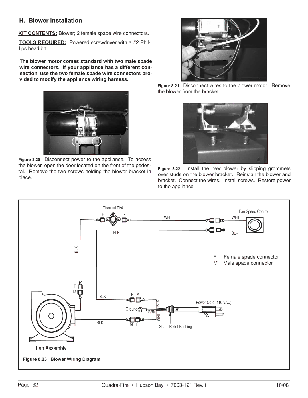
Thermal Disk |
| Fan Speed Control | ||
F | F |
| ||
WHT | WHT | |||
|
| |||
| BLK |
| BLK | |
BLK
F
M
BLK
BLK
F = Female spade connector
M = Male spade connector
F | M |
|
|
|
| BLK | Power Cord (110 VAC) |
Ground |
| ||
GRN |
| ||
|
|
| |
M | F | WHT |
|
Strain Relief Bushing |
| ||
|
|
| |
Fan Assembly
Figure 8.23 Blower Wiring Diagram
|
|
|
|
Page 32 | 10/08 | ||