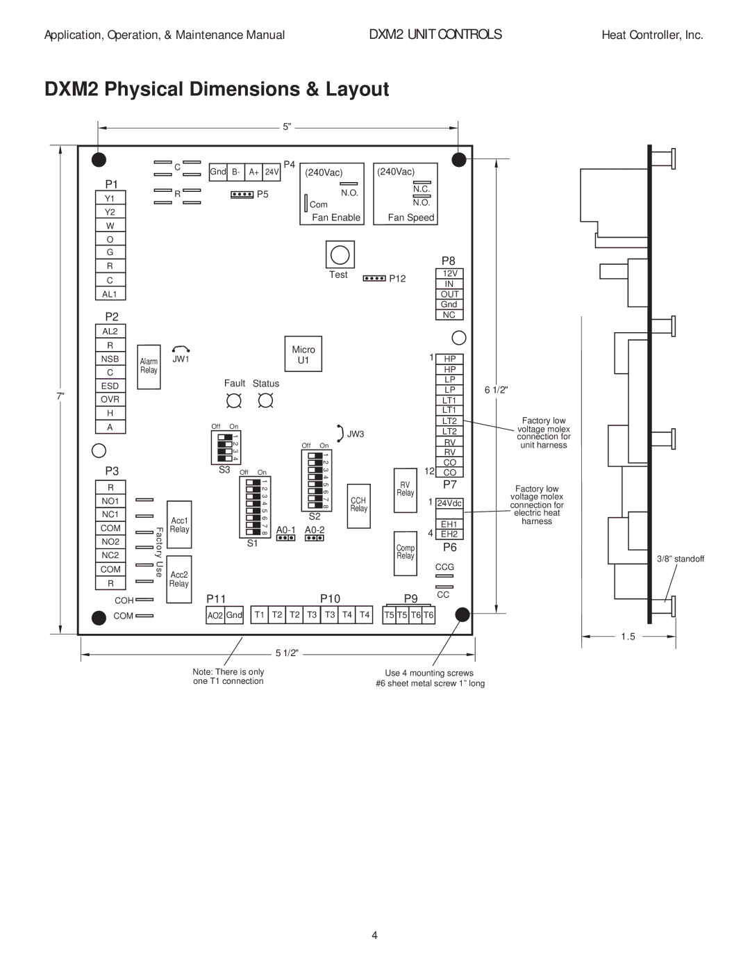
DXM2 specifications
The Heat Controller DXM2 is an advanced heating and cooling solution, meticulously designed for residential and commercial applications. This sophisticated unit integrates modern technologies to deliver superior climate control, ensuring comfort while maintaining energy efficiency. Among its standout features are its intuitive operation, flexibility in installation, and superior performance metrics.One of the key attributes of the DXM2 is its advanced inverter technology, which allows for variable speed operation. This feature enables the system to adjust its output based on real-time cooling or heating demands, resulting in reduced energy consumption and lower utility bills. The inverter technology not only promotes efficiency but also enhances the system's operational longevity, as it reduces the wear and tear typically associated with traditional HVAC systems that operate at fixed speeds.
The unit boasts a user-friendly interface that allows for seamless control. With its advanced remote control and optional smartphone app connectivity, users can effortlessly adjust settings from anywhere, making it a perfect fit for today’s tech-savvy homeowners. This flexibility ensures that comfort can be customized according to personal preferences and schedules.
Additionally, the DXM2 is equipped with a multi-stage filtration system that actively removes dust, allergens, and other airborne particles, contributing to improved indoor air quality. This feature is particularly beneficial for individuals with allergies or respiratory issues, as it ensures cleaner air circulating throughout the living space.
The system’s whisper-quiet operation sets it apart from many competitors in the market. With noise levels comparable to a soft breeze, the DXM2 provides comfort without disruptive sounds, making it ideal for bedrooms, offices, and quiet spaces.
Moreover, the DXM2 offers enhanced durability and reliability due to its robust construction and high-quality components. The unit is designed to withstand harsh weather conditions and varying environments, ensuring consistent performance year-round.
Another noteworthy characteristic is its eco-friendly refrigerant, which aligns with contemporary environmental standards. This selection contributes to lower greenhouse gas emissions while maintaining efficiency and effectiveness in both heating and cooling modes.
In conclusion, the Heat Controller DXM2 is a prominent choice for anyone seeking a reliable and efficient climate control system. Its combination of advanced technology, customizable features, superior air quality management, and low noise levels positions it as a leader in the heating and cooling industry. Ultimately, the DXM2 is engineered to meet the demands of modern living, creating comfortable environments with unparalleled convenience and efficiency.

