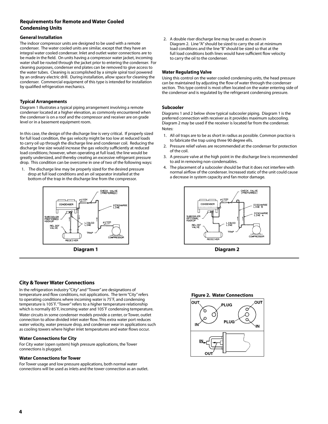
H-IM-CU specifications
Heatcraft Refrigeration Products has long been recognized as a leader in the refrigeration industry, and their H-IM-CU model is a prime example of innovative design and cutting-edge technology. The H-IM-CU is engineered to deliver exceptional performance and efficiency, catering to various commercial refrigeration needs.One of the standout features of the H-IM-CU is its robust construction. The unit is designed with high-quality materials that ensure durability and long-lasting performance in demanding environments. This construction not only protects against wear and tear but also supports the reliable operation essential for business continuity.
The H-IM-CU incorporates advanced cooling technologies that enhance its efficiency. Equipped with a high-efficiency compressor, this model optimizes energy consumption, reducing operational costs while still maintaining optimal refrigerant temperatures. This energy-efficient design is particularly beneficial for businesses looking to minimize their carbon footprint and achieve sustainability goals.
An important characteristic of the H-IM-CU is its user-friendly control system. The intuitive interface allows operators to easily adjust and monitor temperature settings, ensuring that products are stored in favorable conditions. This user-centric design simplifies the management of refrigeration units, making it easier for staff to perform routine tasks.
Additionally, the H-IM-CU features a whisper-quiet operation, which is an advantage for businesses that prioritize a pleasant customer experience. This is achieved through effective sound-dampening technologies and smart engineering that minimize noise without compromising cooling performance.
Another significant highlight is the versatility of the H-IM-CU. It is suitable for a wide range of applications, from convenience stores to restaurants and supermarkets. This adaptability makes it a preferred choice for businesses seeking a reliable refrigeration solution that can cater to their specific needs.
Furthermore, the model boasts enhanced airflow technology that ensures even temperature distribution throughout the unit. This promotes efficient cooling and eliminates hotspots, keeping products at the desired temperature consistently.
Overall, the Heatcraft Refrigeration Products H-IM-CU stands out as a leading choice in commercial refrigeration. With its combination of durability, energy efficiency, user-friendly controls, quiet operation, and versatility, it meets the high standards of modern businesses looking for reliable cooling solutions. Investing in the H-IM-CU not only enhances product longevity but also aids in operational efficiency, making it a wise choice for any commercial refrigeration setup.

