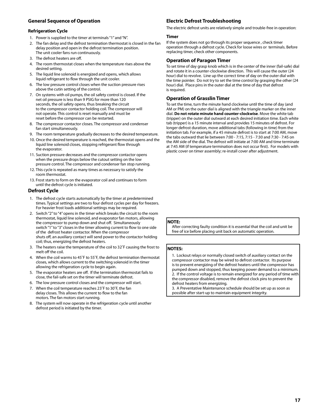
General Sequence of Operation

Refrigeration Cycle

1.Power is supplied to the timer at terminals “1” and “N”.

2.The fan delay and the defrost termination thermostat is closed in the fan delay position and open in the defrost termination position.

The unit cooler fans run continuously.

3.The defrost heaters are off.

4.The room thermostat closes when the temperature rises above the desired setting.

5.The liquid line solenoid is energized and opens, which allows liquid refrigerant to flow through the unit cooler.

6.The low pressure control closes when the suction pressure rises above the cutin setting of the control.

7.On systems with oil pumps, the oil safety control is closed. If the net oil pressure is less than 9 PSIG for more than 120 seconds, the oil safety opens, thus breaking the circuit

to the compressor contactor holding coil. The compressor will not operate. This control is reset manually and must be reset before the compressor can be restarted.

8.The compressor contactor closes. The compressor and condenser fan start simultaneously.

9.The room temperature gradually decreases to the desired temperature.

10.Once the desired temperature is reached, the thermostat opens and the liquid line solenoid closes, stopping refrigerant flow through

the evaporator.

11.Suction pressure decreases and the compressor contactor opens when the pressure drops below the cutout setting on the low pressure control. The compressor and condenser fan stop running.

12.This cycle is repeated as many times as necessary to satisfy the room thermostat.

13.Frost starts to form on the evaporator coil and continues to form until the defrost cycle is initiated.

Defrost Cycle

1.The defrost cycle starts automatically by the timer at predetermined times. Typical settings are two to four defrost cycles per day for freezers. For heavier frost loads additional settings may be required.

2.Switch “2” to “4” opens in the timer which breaks the circuit to the room thermostat, liquid line solenoid, and evaporator fan motors, allowing the compressor to pump down and shut off. Simultaneously

switch “1” to “3” closes in the timer allowing current to flow to one side of the defrost heater contactor. When the compressor

shuts off, an auxiliary contact will send power to the contactor holding coil; thus, energizing the defrost heaters.

3.The heaters raise the temperature of the coil to 32˚F causing the frost to melt off the coil.

4.When the coil warms to 45˚F to 55˚F, the defrost termination thermostat closes, which allows current to the switching solenoid in the timer allowing the refrigeration cycle to begin again.

5.The evaporator heaters are off. If the termination thermostat fails to close, the fail-safe set on the timer will terminate defrost.

6.The low pressure control closes and the compressor will start.

7.When the coil temperature reaches 23˚F to 30˚F, the fan delay closes. This allows the current to flow to the fan motors. The fan motors start running.

8.The system will now operate in the refrigeration cycle until another defrost period is initiated by the timer.

Electric Defrost Troubleshooting

The electric defrost units are relatively simple and trouble-free in operation:

Timer

If the system does not go through its proper sequence , check timer operation through a defrost cycle. Check for loose wires or terminals. Before replacing timer, check other components.

Operation of Paragon Timer

To set time of day grasp knob which is in the center of the inner (fail-safe) dial and rotate it in a counter-clockwise direction. This will cause the outer (24 hour) dial to revolve. Line up the correct time of day on the outer dial with the time pointer. Do not try to set the time control by grasping the other (24 hour) dial. Place pins in the outer dial at the time of day that defrost

is required.

Operation of Grasslin Timer

To set the time, turn the minute hand clockwise until the time of day (and AM or PM) on the outer dial is aligned with the triangle marker on the inner dial. Do not rotate minute hand counter-clockwise. Move the white tab (tripper) on the outer dial outward at each desired initiation time. Each white tab (tripper) is a 15 minute interval and provides 15 minutes of defrost. For longer defrost duration, move additional tabs (following in time) from the initiation tab. For example, if a 45 minute defrost is to start at 7:00 AM, move the tabs outward that lie between 7:00 - 7:15, 7:15 - 7:30 and 7:30 - 7:45 on the AM side of the dial. The defrost will initiate at 7:00 AM and time terminate at 7:45 AM (if temperature termination does not occur first). For models with plastic cover on timer assembly; re-install cover after adjustment.

NOTE:

After correcting faulty condition it is essential that the coil and unit be free of ice before placing unit back on automatic operation.

NOTES:

1.Lockout relays or normally closed switch of auxiliary contact on the compressor contactor may be wired to defrost contactor. Its purpose is to prevent energizing of the defrost heaters until the compressor has pumped down and stopped, thus keeping power demand to a minimum.

2.If the control voltage is to remain energized for any period of time with the compressor disabled, remove the defrost clock pins to prevent the defrost heaters from energizing.

3.A Preventative Maintenance schedule should be set up as soon as possible after start-up to maintain equipment integrity.

17

Page 17
Image 17
Heatcraft Refrigeration Products H-IM-CU General Sequence of Operation, Defrost Cycle, Electric Defrost Troubleshooting

H-IM-CU specifications

Heatcraft Refrigeration Products has long been recognized as a leader in the refrigeration industry, and their H-IM-CU model is a prime example of innovative design and cutting-edge technology. The H-IM-CU is engineered to deliver exceptional performance and efficiency, catering to various commercial refrigeration needs.

One of the standout features of the H-IM-CU is its robust construction. The unit is designed with high-quality materials that ensure durability and long-lasting performance in demanding environments. This construction not only protects against wear and tear but also supports the reliable operation essential for business continuity.

The H-IM-CU incorporates advanced cooling technologies that enhance its efficiency. Equipped with a high-efficiency compressor, this model optimizes energy consumption, reducing operational costs while still maintaining optimal refrigerant temperatures. This energy-efficient design is particularly beneficial for businesses looking to minimize their carbon footprint and achieve sustainability goals.

An important characteristic of the H-IM-CU is its user-friendly control system. The intuitive interface allows operators to easily adjust and monitor temperature settings, ensuring that products are stored in favorable conditions. This user-centric design simplifies the management of refrigeration units, making it easier for staff to perform routine tasks.

Additionally, the H-IM-CU features a whisper-quiet operation, which is an advantage for businesses that prioritize a pleasant customer experience. This is achieved through effective sound-dampening technologies and smart engineering that minimize noise without compromising cooling performance.

Another significant highlight is the versatility of the H-IM-CU. It is suitable for a wide range of applications, from convenience stores to restaurants and supermarkets. This adaptability makes it a preferred choice for businesses seeking a reliable refrigeration solution that can cater to their specific needs.

Furthermore, the model boasts enhanced airflow technology that ensures even temperature distribution throughout the unit. This promotes efficient cooling and eliminates hotspots, keeping products at the desired temperature consistently.

Overall, the Heatcraft Refrigeration Products H-IM-CU stands out as a leading choice in commercial refrigeration. With its combination of durability, energy efficiency, user-friendly controls, quiet operation, and versatility, it meets the high standards of modern businesses looking for reliable cooling solutions. Investing in the H-IM-CU not only enhances product longevity but also aids in operational efficiency, making it a wise choice for any commercial refrigeration setup.