Mode D’EMPLOI ET Instructions DE Securite
Contents
Motor SAW
Product Specifications
English
Power Tool Safety
Table SAW Safety
Guidelines for Extension Cords
Electrical Requirements and Safety
Power Supply Requirements
Extension Cord Requirements Grounding Instructions
Carton Contents
Accessories and Attachments
Tools Needed for Assembly
Unpacking Your Jobsite Table SAW
Know Your Jobsite Table SAW
Blade Elevation Handwheel Raises
Glossary of Terms
Table SAW Terms
Woodworking Terms
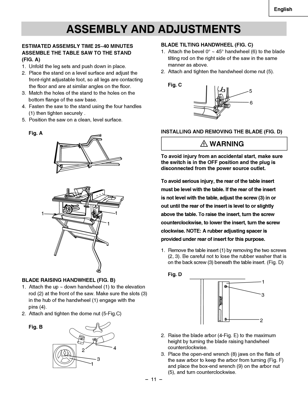
Blade Raising Handwheel FIG. B
Assembly and Adjustments
Installing and Removing the Blade FIG. D
Blade Tilting Handwheel FIG. C
Fig. E
Blade Guard Assembly FIG. G, H
Blade Tilt Pointer
Adjusting the 9000 and 45 Positive Stops FIG. J, K, L
Stop
Rip fence and miter gauge Fig. O
Blade Parallel to the Miter Gauge Groove FIG. M, N
If the blade is partial to left side
Storage FIG. O, P
Miter Gauge Operation FIG. Q
Miter Gauge Adjustment FIG. Q
RIP Fence Adjustment FIG. S
Blade Fig. P
Table Extension Scale Pointer FIG. T-1
RIP Fence Indicator FIG. T
Adjusting the Cutting Line Indicator FIG. U
Adjusting CAM Locking Lever FIG
Basic SAW Operations
Operation
Ripping FIG. AA, BB
Cutting Operations
Bevel Crosscutting FIG. EE
Bevel Ripping
Ripping Small Pieces
Crosscutting FIG. CC
Miter Cuts FIG. GG
Using Wood Facing on the RIP Fence FIG. HH
Compound Miter Crosscutting FIG. FF
Auxiliary Fence FIG
Dado Cuts FIG. KK
Fig. JJ
Blade Raising and Tilting Mechanism FIG. LL
Maintenance
General Maintenance
Maintaining Your Table SAW
Symptom Possible Causes Corrective Action
Troubleshooting Guide
Push Stick Construction
Scie
Specifications Produit
Français
Moteur
Avertissement
Consignes DE Sécurité SUR LES Outils
Consignes DE Sécurité SUR LA Scie À Table
Directives Concernant LES Rallonges
Exigences Électriques ET Sécurité
Exigences Concernant L’ Alimentation Électrique
Exigences Concernant LES Rallonges
Contenu DE LA Boîte
Accessoires
Outils Requis Pour Assemblage
Déballage DE LA Scie À Table DE Chantier
Apprendre À Connaître LA Scie À Table DE Chantier
Termes DE Menuiserie
Glossaire
Termes Relatifs À LA Scie À Table Qualité PRO Craftsman
Manivelle D’ELEVATION DE LA Lame FIG. B
Installation ET Remplacement DE LA Lame FIG. D
Assemblage ET Réglages
Manivelle D’INCLINAISON DE LA Lame FIG. C
Montage DU Protecteur DE Lame FIG. G, H
Fig. F
Indicateur D’INCLINAISON DE Lame
Provoquer un retour et des blessures graves
Réglage DES Butées Fixes À 9000 ET 45 FIG. J, K, L
Butée
Guide de refente et jauge à onglets Fig. O
Lame Parallèle À LA Rainure DE LA Jauge À Onglets FIG. M, N
Si la lame est partiellement à gauche
Rangement FIG. O, P
Reglage DU Guide DE Coupe DE FIL FIG. S
Lame Fig. P
Reglage DU Guide DE Coupe DE FIL FIG. Q
Utilisation DU Guide DE Coupe D’ONGLET FIG. Q
Fig. T-1 Reglage DE L’INDICATEUR DE Ligne DE Coupe Fig. U
Indicateur D’ÉCHELLE DE Rallonge DE Table FIG. T-1
Fonctions DE Base DE LA Scie
Utilisation
Sciage EN Long FIG.AA, BB
Opérations DE Coupe
Tronçonnage EN Biseau FIG. EE
Coupe EN Long EN Biseau
Coupe EN Long DE Petites Pièces
Tronçonnage FIG.CC
Guide Auxiliaire FIG
Coupe Transversale D’ONGLET DE Type Mixte FIG. FF
Coupes D’ONGLET FIG. GG
Rainurage FIG. KK
Avec deux attaches C. Fig. JJ
Lubrification
Entretien
Entretien DE LA Scie À Table
Entretien Général
Problème Causes Possibles Mesures Correctives
Guide DE Dépannage
Fabrication D’UN Poussoir
Motor Siera
Especificaciones DEL Producto
Español
Seguridad DE LA Herramienta Eléctrica
Seguridad EN EL Manejo DE LA Sierra DE Mesa
Indicaciones Para LOS Cablesprolongadores
Requisitos Electricos Y Seguridad
Requisitos DE LA Fuente Dealimentación
Requisitos DE LOS Cablesprolongadores
Contenido DE LA Caja
Accesorios Y Acoples
Cómo Desempacar SU Sierra DE Mesa Para EL Lugar DE Trabajo
La parte trasera de la sierra de mesa
Interruptor DE Reinicio POR Sobrecarga
Glosario DE Terminos
Términos DE LA Sierra DE Mesa
Terminos DE Carpinteria
Manivela DE Elevación DE LA Hoja FIG. B
Montaje Y Ajustes
Manivela DE Inclinación DE LA Hoja FIG. C
Instalación Y Cambio DE LA Hoja FIG. D
Conjunto Protector DE Hoja FIG. G, H
Parada a
Provocar un retroceso de la herramienta y heridas
Graves
Ajuste DE LAS Paradas Positivas DE 900 Y 45 FIG. J, K, L
Fig. O Arrollamiento de los cables Fig. O-1
Almacenaje FIG. O, P
Ajuste DEL SEPARADOR-LIMITADOR FIG. S
Español Hoja Fig. P
Ajuste DE LA Guía DE Ingletes FIG. Q
Funcionamiento DE LA Guía DE Ingletes FIG.Q
Cómo Ajustar LA Palanca DE Bloqueo DE LA Leva FIG
Indicador DE LA Escala DE Extensión DE LA Mesa FIG. T-1
Ajuste EL Indicador DE Línea DEL Corte FIG. U
Funcionamiento Elemental DE LA Sierra
Funcionamiento
Corte EN Direccion a LA Veta FIG. AA, BB
Operaciones DE Corte
USO DE Caras DE Madera EN LA Guía DE Ingletes FIG. DD
Corte AL Hilo EN Bisel
Corte AL Hilo DE Piezas Pequeñas
Corte Transversal FIG.CC
Union DE Inglete FIG. GG
Corte Compuesto DE Ingletes FIG. FF
Tope Auxiliar FIG
Fabricación del lateral
Cortes DE Ranura FIG. KK
En forma de C. Fig. JJ
Mecanismo DE Elevación E Inclinación DE LA Hoja FIG. LL
Mantenimiento
Mantenimiento DE LA Sierra DE Mesa
Mantenimiento General
Problema Causas DEL Problema Solucion
Guia Para LA Solucion DE Problemas
Construccion DEL Empujador
Always order by I.D. Number
Parts List
Parts List for Schematic
Jobsite Table SAW Model NO. C10RA3
Jobsite Table SAW Model NO. C10RA3
QTY
Jobsite Table SAW Model NO. C10RA3 Part List for Stand
Hitachi Koki Canada Co