Facility names and functions (Front)
1
4
2
5
3
31 ![]()
![]() 6
6
7
11 ![]()
![]() 9
9
8 ![]()
![]() 10
10
12
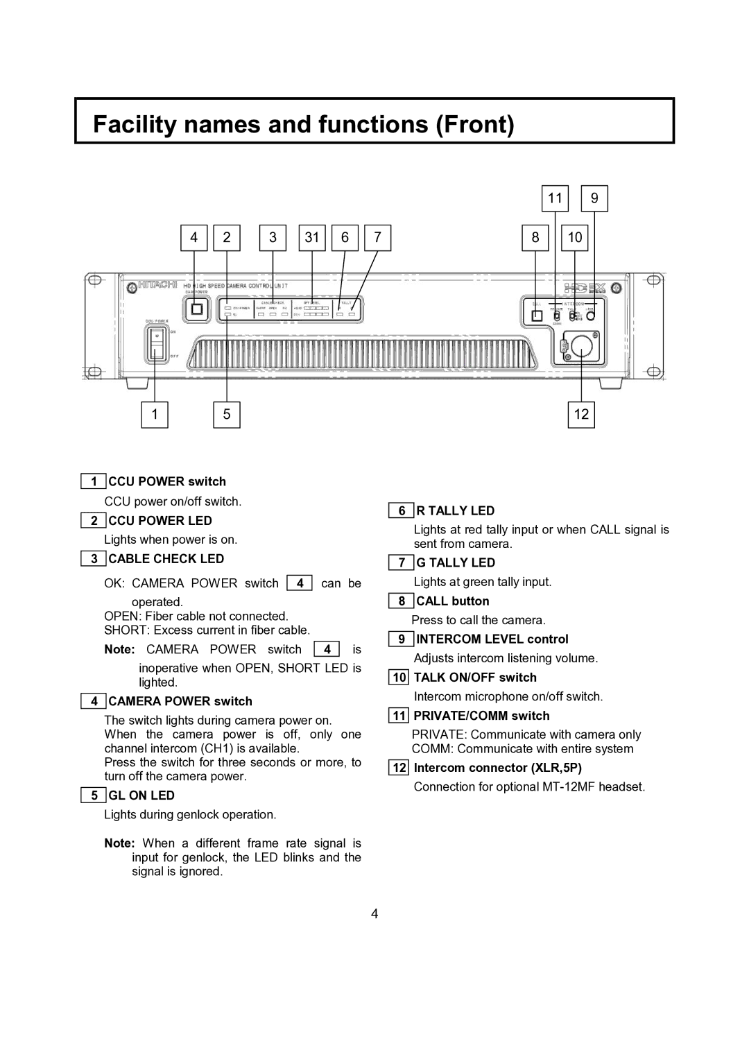
1 CCU POWER switch
CCU power on/off switch.
2CCU POWER LED Lights when power is on.
3 CABLE CHECK LED
OK: CAMERA POWER switch 4 can be
operated.
OPEN: Fiber cable not connected.
SHORT: Excess current in fiber cable.
Note: CAMERA POWER switch 4 is
inoperative when OPEN, SHORT LED is lighted.
4 CAMERA POWER switch
The switch lights during camera power on. When the camera power is off, only one channel intercom (CH1) is available.
Press the switch for three seconds or more, to turn off the camera power.
5 GL ON LED
Lights during genlock operation.
Note: When a different frame rate signal is input for genlock, the LED blinks and the signal is ignored.
6 R TALLY LED
Lights at red tally input or when CALL signal is sent from camera.
7 G TALLY LED
Lights at green tally input.
8 CALL button
Press to call the camera.
9INTERCOM LEVEL control Adjusts intercom listening volume.
10TALK ON/OFF switch
Intercom microphone on/off switch.
11PRIVATE/COMM switch
PRIVATE: Communicate with camera only
COMM: Communicate with entire system
12Intercom connector (XLR,5P) Connection for optional
4