System Configuration
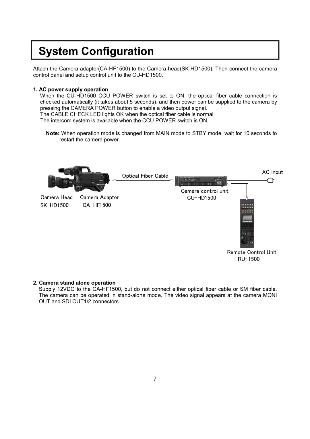
Attach the Camera adapter(CA-HF1500) to the Camera head(SK-HD1500). Then connect the camera control panel and setup control unit to the CU-HD1500.
1. AC power supply operation
When the CU-HD1500 CCU POWER switch is set to ON, the optical fiber cable connection is checked automatically (it takes about 5 seconds), and then power can be supplied to the camera by pressing the CAMERA POWER button to enable a video output signal.
The CABLE CHECK LED lights OK when the optical fiber cable is normal. The intercom system is available when the CCU POWER switch is ON.
Note: When operation mode is changed from MAIN mode to STBY mode, wait for 10 seconds to restart the camera power.
| | Camera control unit |
Camera Head | Camera Adaptor | CU-HD1500 |
SK-HD1500 | CA-HF1500 | |
Remote Control Unit
RU- 1500
2.Camera stand alone operation
Supply 12VDC to the CA-HF1500, but do not connect either optical fiber cable or SM fiber cable. The camera can be operated in stand-alone mode. The video signal appears at the camera MONI OUT and SDI OUT1/2 connectors.