Facility names and functions (Rear & Front)
26 COMMUNICATION connector
Intercom and tally signals are input from external system.
27 WFM CONTROL connector
This connector is used to select the display mode of the waveform monitor.
28 TRUNK connector
Use for communication with TRUNK connector on
29TALLY OUT connector Contact outputs for tally signals.
30TALLY CONTACT/VOLTAGE
The TALLY input can be contact or voltage supply.
Set the TALLY switches according to the systems connected to the COMMUNICATION connector on rear panel.
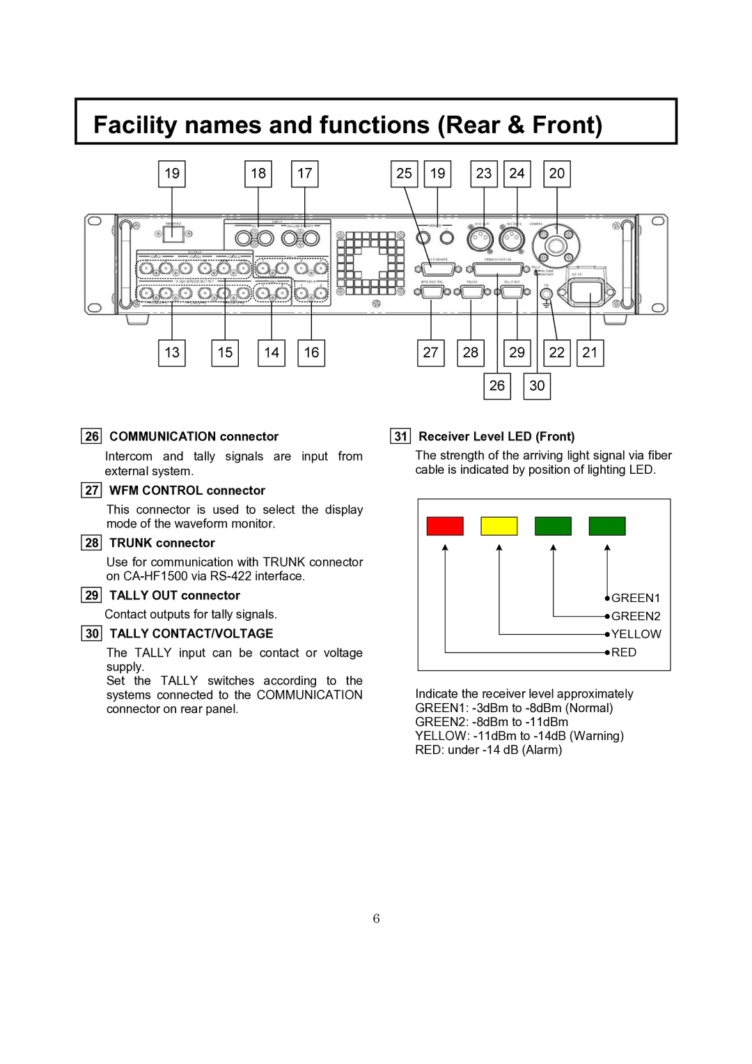
31 Receiver Level LED (Front)
The strength of the arriving light signal via fiber cable is indicated by position of lighting LED.
GREEN1 |
GREEN2 |
YELLOW |
RED |
Indicate the receiver level approximately GREEN1:
6