54
A
36 | 55 | |
33 | ||
34 | ||
| ||
223 |
| |
112 | 52 | |
10 | ||
TORQUE | ||
58 | ||
TO |
70 ft±lb
(95 N.m)
38
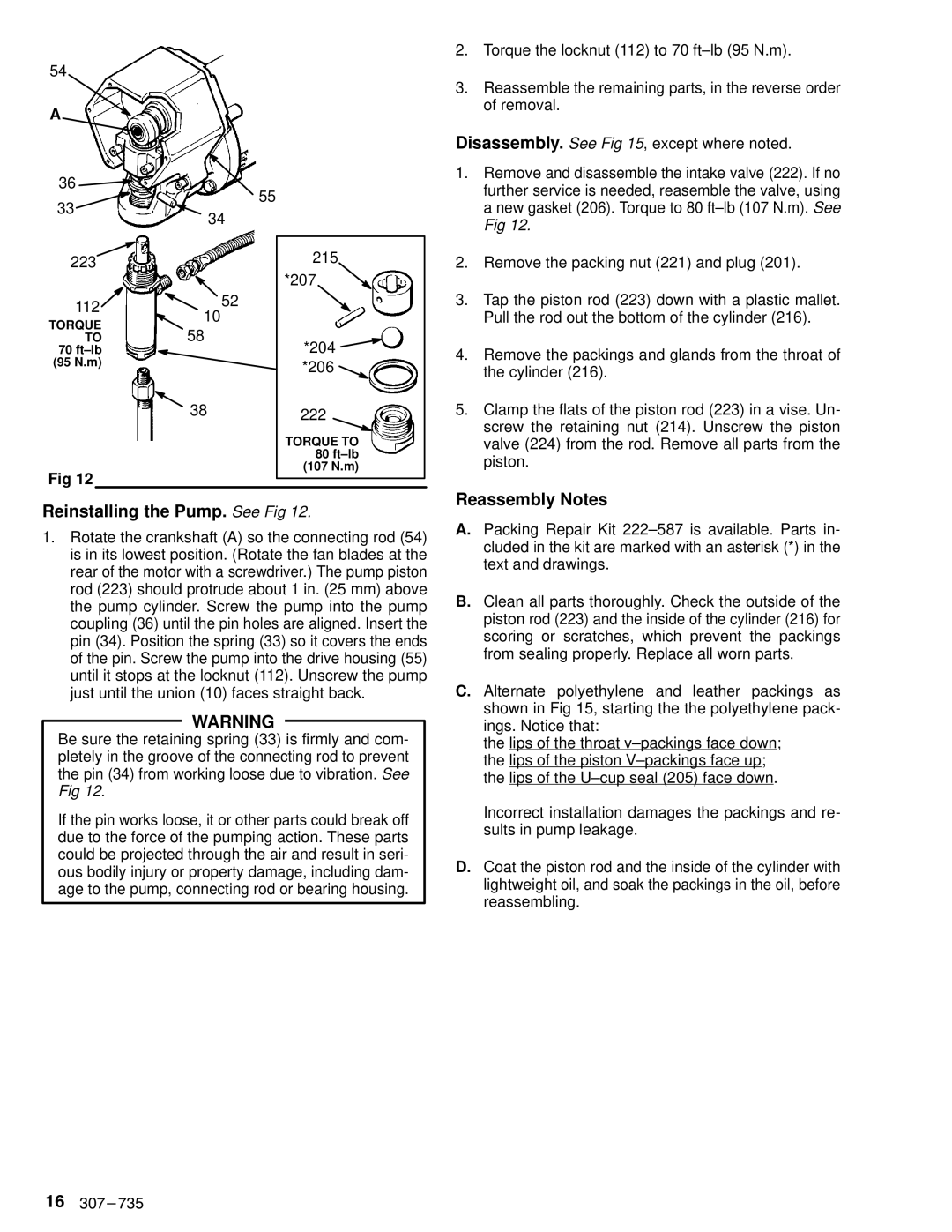
Fig 12
215
*207
*204 ![]()
*206 ![]()
222
TORQUE TO
80ft±lb
(107 N.m)
2.Torque the locknut (112) to 70 ft±lb (95 N.m).
3.Reassemble the remaining parts, in the reverse order of removal.
Disassembly. See Fig 15, except where noted.
1.Remove and disassemble the intake valve (222). If no further service is needed, reasemble the valve, using a new gasket (206). Torque to 80 ft±lb (107 N.m). See Fig 12.
2.Remove the packing nut (221) and plug (201).
3.Tap the piston rod (223) down with a plastic mallet. Pull the rod out the bottom of the cylinder (216).
4.Remove the packings and glands from the throat of the cylinder (216).
5.Clamp the flats of the piston rod (223) in a vise. Un- screw the retaining nut (214). Unscrew the piston valve (224) from the rod. Remove all parts from the piston.
Reinstalling the Pump. See Fig 12.
1.Rotate the crankshaft (A) so the connecting rod (54) is in its lowest position. (Rotate the fan blades at the rear of the motor with a screwdriver.) The pump piston rod (223) should protrude about 1 in. (25 mm) above the pump cylinder. Screw the pump into the pump coupling (36) until the pin holes are aligned. Insert the pin (34). Position the spring (33) so it covers the ends of the pin. Screw the pump into the drive housing (55) until it stops at the locknut (112). Unscrew the pump just until the union (10) faces straight back.
WARNING
Be sure the retaining spring (33) is firmly and com- pletely in the groove of the connecting rod to prevent the pin (34) from working loose due to vibration. See Fig 12.
If the pin works loose, it or other parts could break off due to the force of the pumping action. These parts could be projected through the air and result in seri- ous bodily injury or property damage, including dam- age to the pump, connecting rod or bearing housing.
Reassembly Notes
A.Packing Repair Kit 222±587 is available. Parts in- cluded in the kit are marked with an asterisk (*) in the text and drawings.
B.Clean all parts thoroughly. Check the outside of the piston rod (223) and the inside of the cylinder (216) for scoring or scratches, which prevent the packings from sealing properly. Replace all worn parts.
C.Alternate polyethylene and leather packings as shown in Fig 15, starting the the polyethylene pack- ings. Notice that:
the lips of the throat v±packings face down; the lips of the piston V±packings face up; the lips of the U±cup seal (205) face down.
Incorrect installation damages the packings and re- sults in pump leakage.
D.Coat the piston rod and the inside of the cylinder with lightweight oil, and soak the packings in the oil, before reassembling.
16