Air Motor Service
M2
30 31 37 | 54 | 28 |
3 |
| 34† |
L |
| 33† |
|
| 45† |
|
| 32† |
1
59
55
58 53† 33† 45†
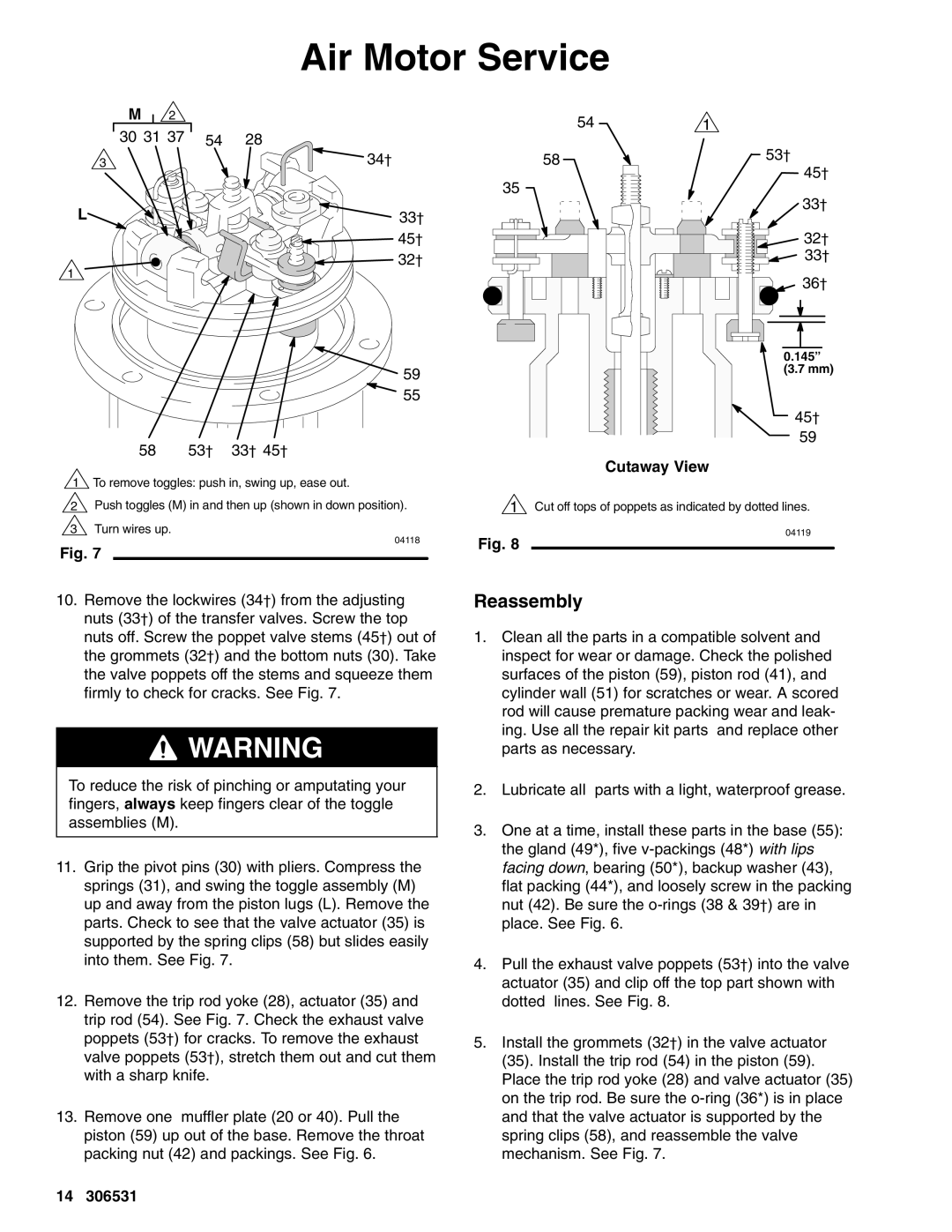
1 To remove toggles: push in, swing up, ease out.
2Push toggles (M) in and then up (shown in down position).
3Turn wires up.
04118
Fig. 7
10.Remove the lockwires (34†) from the adjusting nuts (33†) of the transfer valves. Screw the top nuts off. Screw the poppet valve stems (45†) out of the grommets (32†) and the bottom nuts (30). Take the valve poppets off the stems and squeeze them firmly to check for cracks. See Fig. 7.
![]() WARNING
WARNING
To reduce the risk of pinching or amputating your fingers, always keep fingers clear of the toggle assemblies (M).
11.Grip the pivot pins (30) with pliers. Compress the springs (31), and swing the toggle assembly (M) up and away from the piston lugs (L). Remove the parts. Check to see that the valve actuator (35) is supported by the spring clips (58) but slides easily into them. See Fig. 7.
12.Remove the trip rod yoke (28), actuator (35) and trip rod (54). See Fig. 7. Check the exhaust valve poppets (53†) for cracks. To remove the exhaust valve poppets (53†), stretch them out and cut them with a sharp knife.
13.Remove one muffler plate (20 or 40). Pull the piston (59) up out of the base. Remove the throat packing nut (42) and packings. See Fig. 6.
541
58 | 53† |
|
45†
35
33†
![]() 32†
32†
33†
![]() 36†
36†
0.145” (3.7 mm)
45†
59
Cutaway View
1Cut off tops of poppets as indicated by dotted lines.
04119
Fig. 8
Reassembly
1.Clean all the parts in a compatible solvent and inspect for wear or damage. Check the polished surfaces of the piston (59), piston rod (41), and cylinder wall (51) for scratches or wear. A scored rod will cause premature packing wear and leak- ing. Use all the repair kit parts and replace other parts as necessary.
2.Lubricate all parts with a light, waterproof grease.
3.One at a time, install these parts in the base (55): the gland (49*), five
4.Pull the exhaust valve poppets (53†) into the valve actuator (35) and clip off the top part shown with dotted lines. See Fig. 8.
5.Install the grommets (32†) in the valve actuator (35). Install the trip rod (54) in the piston (59). Place the trip rod yoke (28) and valve actuator (35) on the trip rod. Be sure the
14 306531