SECTION 5 – OPERATION
5-1. Controls
6
1
8
7
2
3
5
4
Ref.
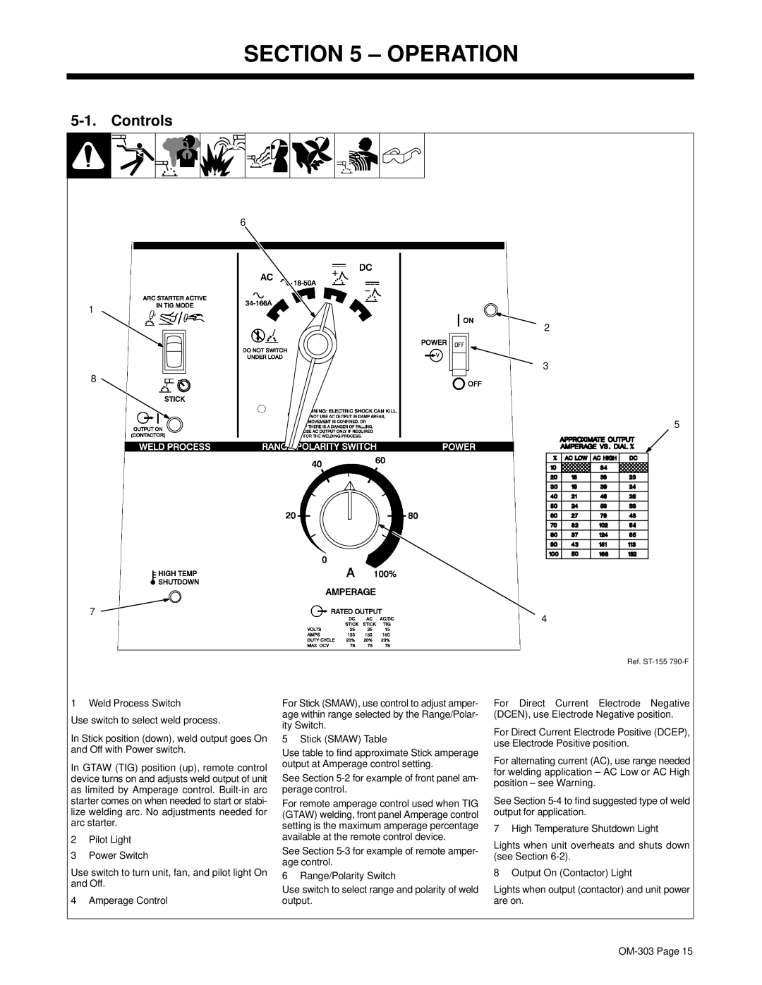
1 Weld Process Switch
Use switch to select weld process.
In Stick position (down), weld output goes On and Off with Power switch.
In GTAW (TIG) position (up), remote control device turns on and adjusts weld output of unit as limited by Amperage control.
2Pilot Light
3Power Switch
Use switch to turn unit, fan, and pilot light On and Off.
4 Amperage Control
For Stick (SMAW), use control to adjust amper- age within range selected by the Range/Polar- ity Switch.
5 Stick (SMAW) Table
Use table to find approximate Stick amperage output at Amperage control setting.
See Section 5-2 for example of front panel am- perage control.
For remote amperage control used when TIG (GTAW) welding, front panel Amperage control setting is the maximum amperage percentage available at the remote control device.
See Section
6 Range/Polarity Switch
Use switch to select range and polarity of weld output.
For Direct Current Electrode Negative (DCEN), use Electrode Negative position.
For Direct Current Electrode Positive (DCEP), use Electrode Positive position.
For alternating current (AC), use range needed for welding application – AC Low or AC High position – see Warning.
See Section
7 High Temperature Shutdown Light
Lights when unit overheats and shuts down (see Section
8 Output On (Contactor) Light
Lights when output (contactor) and unit power are on.