Manuals
/
Hobart
/
Computer Equipment
/
Power Supply
Hobart
OM-303
manual
Electrical Diagrams, Circuit Diagram
Models:
OM-303
1
23
32
32
Download
32 pages
996 b
20
21
22
23
24
25
26
27
Troubleshooting
Specifications
Install
Parts list
Electrical Diagrams
Symbol Usage
Connecting Input Power
Main Assembly
General Precautionary Label
Safety
Page 23
Image 23
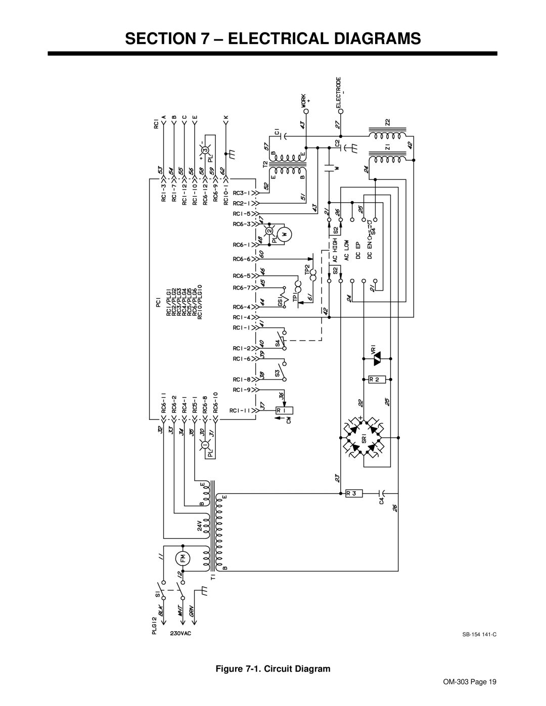
SECTION 7 – ELECTRICAL DIAGRAMS
SB-154
141-C
Figure
7-1.
Circuit Diagram
OM-303
Page 19
Page 22
Page 24
Page 23
Image 23
Page 22
Page 24
Contents
Processes
OM-303155795N
Description
From Hobart to You
Table of Contents
Page
Electric Shock can kill
Symbol Usage
Marks a special safety message
Arc Welding Hazards
Buildup of GAS can injure or kill
ARC Rays can burn eyes and skin
Welding can cause fire or explosion
Flying Metal can injure eyes
Principal Safety Standards
About Pacemakers
EMF Information
LES Fumé ES ET LES GAZ peuvent ê tre dangereux
Signification des symboles
Consignes DE Securite Lire Avant Utilisation
UN Choc É Lectrique peut tuer
LE Bruit peut affecter l’ouïe
LE Soudage peut provoquer un incendie ou une explosion
DES Particules Volantes peuvent blesser les yeux
DES Organes Mobiles peuvent provoquer des blessures
Risque D’INCENDIE OU
LA Chute DE L’APPAREIL peut blesser
’EMPLOI Excessif peut
Consignes relatives aux stimulateurs cardiaques
Principales normes de sé curité
Information sur les champs é lectromagné tiques
Definitions
General Precautionary Label
Included with Your Unit
Symbols And Definitions
Introduction
Hertz Models
Specifications
Duty Cycle Chart
Volt-Ampere Curves
Typical Stick Connections
Installation
Turn Off power before mak- ing connections
Selecting a Location
Typical TIG Connections
Connecting Input Power
Electrical Service Guide
Controls
Operation
AC Low AC High
Example of Front Panel Amperage Control
Example of Remote Amperage Control
Gtaw Welding Amperage Range
Process and Material Thickness Guide Label
Troubleshooting
Maintenance and Troubleshooting
Routine Maintenance
Circuit Diagram
Electrical Diagrams
Weld Zone
Incorrect Installation
High Frequency
Welding Processes Requiring High Frequency
Metal Building Requirements
Correct Installation
Metal Building
Main Assembly
Parts List
Dia Part Description Mkgs Quantity
Figure -1. Main Assembly
Page
Page
Support
Service
Hobart Welding Products
Contact your Distributor for
Top
Page
Image
Contents