Item | Dia. | Part | Description |
|
No. | Mkgs. | No. | Quantity | |
|
|
| Figure Figure |
|
|
|
|
|
|
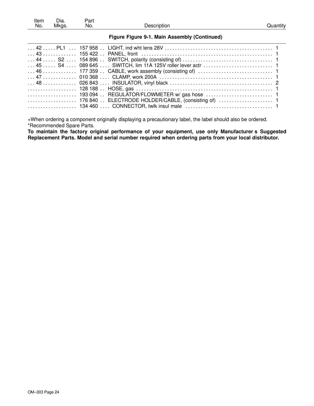
. . . 42 . . . . | . PL1 . . . | 157 958 . . | LIGHT, ind wht lens 28V | . . . 1 |
. . . 43 . . . . | . . . . . . . . . | 155 422 . . | PANEL, front | . . . 1 |
. . . 44 . . . . | . S2 . . . . | 154 896 . . | SWITCH, polarity (consisting of) | . . . 1 |
. . . 45 . . . . | . S4 . . . . | 089 645 . . . | . SWITCH, lim 11A 125V roller lever actr | . . . 1 |
. . . 46 . . . . | . . . . . . . . . | 177 359 . . | CABLE, work assembly (consisting of) | . . . 1 |
. . . 47 . . . . | . . . . . . . . . | 010 368 . . . | . CLAMP, work 200A | . . . 1 |
. . . 48 . . . . | . . . . . . . . . | 026 843 . . . | . INSULATOR, vinyl black | . . . 2 |
. . . . . . . . . . | . . . . . . . . . | 128 188 . . | HOSE, gas | . . . 1 |
. . . . . . . . . . | . . . . . . . . . | 193 094 . . | REGULATOR/FLOWMETER w/ gas hose | . . . 1 |
. . . . . . . . . . | . . . . . . . . . | 176 840 . . | ELECTRODE HOLDER/CABLE, (consisting of) | . . . 1 |
. . . . . . . . . . | . . . . . . . . . | 134 460 . . . | . CONNECTOR, twlk insul male | . . . 1 |
+When ordering a component originally displaying a precautionary label, the label should also be ordered. *Recommended Spare Parts.
To maintain the factory original performance of your equipment, use only Manufacturer’s Suggested Replacement Parts. Model and serial number required when ordering parts from your local distributor.
