1 | 2 | 3 | 4 |
|
|
| 5 |
115V |
|
| 230V |
|
|
|
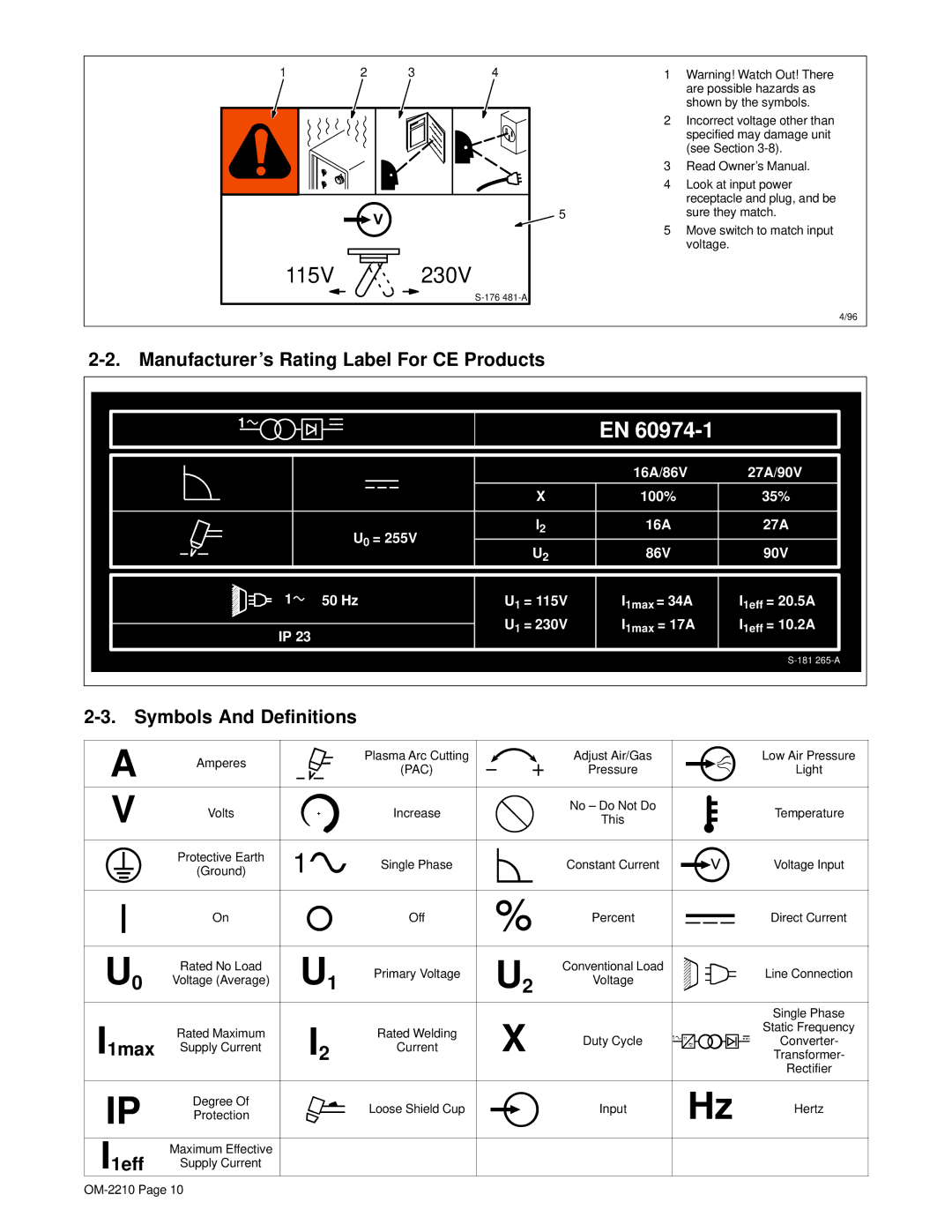
1Warning! Watch Out! There are possible hazards as shown by the symbols.
2Incorrect voltage other than specified may damage unit (see Section
3Read Owner’s Manual.
4Look at input power receptacle and plug, and be sure they match.
5Move switch to match input voltage.
4/96
2-2. Manufacturer’s Rating Label For CE Products
1![]()
EN
| 16A/86V | 27A/90V |
X | 100% | 35% |
I2 | 16A | 27A |
U0 = 255V | 86V | 90V |
U2 |
1![]() 50 Hz
50 Hz
IP 23
U1 = 115V
U1 = 230V
I1max = 34A I1max = 17A
I1eff = 20.5A I1eff = 10.2A
|
|
|
|
|
|
|
|
|
|
|
|
|
|
|
|
|
|
|
|
|
|
|
|
|
|
|
|
|
|
|
| |
|
|
|
|
|
|
|
|
|
|
|
|
|
|
|
|
|
|
|
|
|
|
|
|
|
|
|
|
|
|
| ||
|
|
|
|
|
|
|
|
|
|
|
|
|
|
|
|
|
|
|
| |||||||||||||
|
|
|
|
|
|
|
|
|
|
|
|
|
|
|
|
|
|
|
|
|
|
|
|
|
|
|
|
|
|
|
|
|
A | Amperes |
|
|
|
|
| Plasma Arc Cutting |
|
|
| Adjust Air/Gas |
|
|
|
|
|
|
|
|
|
|
|
|
| Low Air Pressure | |||||||
|
|
|
|
|
|
|
|
|
|
|
|
|
|
|
|
|
|
|
|
|
|
|
|
|
|
|
|
| ||||
|
|
|
|
|
|
|
|
|
|
|
|
| (PAC) |
|
|
| Pressure |
|
|
|
|
|
|
|
|
|
|
|
|
| Light | |
|
|
|
|
|
|
|
|
|
|
|
|
|
|
|
|
|
|
|
|
|
|
|
|
|
|
|
|
|
| |||
|
|
|
|
|
|
|
|
|
|
|
|
|
|
|
|
|
|
|
|
|
|
|
|
|
|
|
|
|
|
|
|
|
V | Volts |
|
|
|
|
| Increase |
|
|
| No – Do Not Do |
|
|
|
|
|
|
|
|
|
|
|
|
| Temperature | |||||||
|
|
|
|
|
|
|
|
|
|
|
|
|
|
|
|
|
|
|
|
| ||||||||||||
|
|
|
|
|
|
|
|
|
|
|
|
|
|
|
|
|
|
|
|
| ||||||||||||
|
|
|
|
|
|
|
| This |
|
|
|
|
|
|
|
|
|
|
|
|
| |||||||||||
|
|
|
|
|
|
|
|
|
|
|
|
|
|
|
|
|
|
| ||||||||||||||
|
|
|
|
|
|
|
|
|
|
|
|
|
|
|
|
|
|
|
|
|
|
|
| |||||||||
|
|
|
|
|
|
|
|
|
|
|
|
|
|
|
|
|
|
|
|
|
|
|
| |||||||||
|
|
|
|
|
|
|
|
|
|
|
|
|
|
|
|
|
|
|
|
|
|
|
|
|
|
|
|
|
|
|
|
|
|
|
|
|
|
|
|
| Protective Earth |
|
|
|
|
| Single Phase |
|
|
| Constant Current |
|
|
|
|
|
|
|
|
|
|
|
|
| Voltage Input |
|
|
|
|
|
|
|
|
|
|
|
|
|
|
|
|
|
|
|
|
|
|
|
|
|
|
|
|
| ||||
|
|
|
|
|
|
|
| (Ground) |
|
|
|
|
|
|
|
|
|
|
|
|
|
|
|
|
|
|
|
|
| |||
|
|
|
|
|
|
|
|
|
|
|
|
|
|
|
|
|
|
|
|
|
|
|
|
|
|
|
|
|
|
|
| |
|
|
|
|
|
|
|
|
|
|
|
|
|
|
|
|
|
|
|
|
|
|
|
|
|
|
|
|
|
|
|
| |
|
|
|
|
|
|
|
|
|
|
|
|
|
|
|
|
|
|
|
|
|
|
|
|
|
|
|
|
|
|
|
|
|
|
|
|
|
|
|
|
| On |
|
|
|
|
| Off |
|
|
| Percent |
|
|
|
|
|
|
|
|
|
|
|
|
| Direct Current |
|
|
|
|
|
|
|
|
|
|
|
|
|
|
|
|
|
|
|
|
|
|
|
|
|
|
|
|
| ||||
|
|
|
|
|
|
|
|
|
|
|
|
|
|
|
|
|
|
|
|
|
|
|
|
|
|
| ||||||
|
|
|
|
|
|
|
|
|
|
|
|
|
|
|
|
|
|
|
|
|
|
|
|
|
|
|
|
|
|
|
|
|
|
|
|
|
|
|
|
|
|
|
|
|
|
|
|
|
|
|
|
|
|
|
|
|
|
|
|
|
|
|
|
|
|
U0 | Rated No Load |
| U1 | Primary Voltage |
| U2 | Conventional Load |
|
|
|
|
|
|
|
|
|
|
|
|
| Line Connection | |||||||||||
|
|
|
|
|
|
|
|
|
|
|
|
|
|
| ||||||||||||||||||
Voltage (Average) |
|
| Voltage |
|
|
|
|
|
|
|
|
|
|
|
|
| ||||||||||||||||
|
|
|
|
|
|
|
|
|
|
|
|
|
|
|
|
| ||||||||||||||||
|
|
|
|
|
|
|
|
|
|
|
|
|
|
|
|
| ||||||||||||||||
|
|
|
|
|
|
|
|
|
|
|
|
|
|
|
|
|
|
|
|
|
|
|
|
|
|
|
|
|
|
|
|
|
I1max |
|
|
| I2 |
|
|
| X |
|
|
|
|
|
|
|
|
|
|
|
|
|
| Single Phase | |||||||||
Rated Maximum |
|
| Rated Welding |
|
|
|
|
|
|
|
|
|
|
|
|
|
|
|
| Static Frequency | ||||||||||||
Supply Current |
|
| Current |
|
| Duty Cycle |
|
|
|
|
|
|
|
|
|
|
|
|
| Converter- | ||||||||||||
|
|
|
|
|
|
|
|
|
|
|
|
|
|
|
|
|
| Transformer- | ||||||||||||||
|
|
|
|
|
|
|
|
|
|
|
|
|
|
|
|
|
|
|
|
|
|
|
|
|
|
|
|
|
|
|
| Rectifier |
|
|
|
|
|
|
|
|
|
|
|
|
|
|
|
|
|
|
|
|
|
|
|
|
|
|
|
|
|
|
|
|
|
IP | Degree Of |
|
|
|
|
| Loose Shield Cup |
|
|
| Input |
|
| Hz |
|
| Hertz | |||||||||||||||
Protection |
|
|
|
|
|
|
|
|
|
|
|
| ||||||||||||||||||||
|
|
|
|
|
|
|
|
|
|
|
|
|
|
| ||||||||||||||||||
|
|
|
|
|
|
|
|
|
|
|
|
|
|
|
|
|
|
|
|
|
|
|
|
|
|
|
|
|
|
|
|
|
I1eff | Maximum Effective |
|
|
|
|
|
|
|
|
|
|
|
|
|
|
|
|
|
|
|
|
|
|
|
| |||||||
Supply Current |
|
|
|
|
|
|
|
|
|
|
|
|
|
|
|
|
|
|
|
|
|
|
|
| ||||||||
|
|
|
|
|
|
|
|
|
|
|
|
|
|
|
|
|
|
|
|
|
|
|
|
|
|
|
|
|
|
|
| |
|
|
|
|
|
|
|
|
|
|
|
|
|
|
|
|
|
|
|
|
|
|
|
|
|
|
|
|
|
|
|
|
|