Manuals
/
Hobart Welding Products
/
Power Tools
/
Welding System
Hobart Welding Products
OM-945 194 047U
manual
Maintenance Label Kohler-Powered Units
Models:
OM-945 194 047U
1
34
64
64
Download
64 pages
36.62 Kb
31
32
33
34
35
36
37
38
Troubleshooting
Specs
Poor Weld Bead Characteristics
Install
Parts list
Electrical Diagram
Symbol Usage
Connecting the Battery
Main Assembly
Do not overfill battery cells
Page 34
Image 34
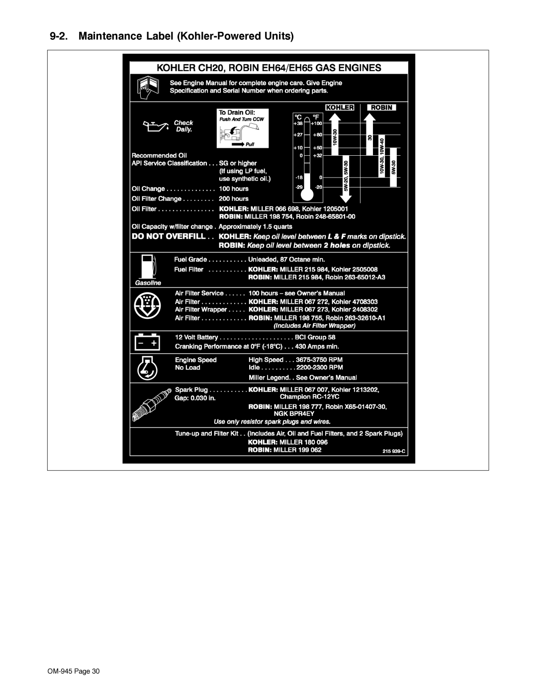
9-2.
Maintenance Label
(Kohler-Powered
Units)
OM-945
Page 30
Page 33
Page 35
Page 34
Image 34
Page 33
Page 35
Contents
Processes
Description
From Hobart to You
Table of Contents
Table of Contents
Symbol Usage
Arc Welding Hazards
Engine Hazards
Compressed Air Hazards
EMF Information
Principal Safety Standards
California Proposition 65 Warnings
Radiation can cause interference
UN Choc Électrique peut tuer
Signification des symboles
− Consignes DE Sécurité − Lire Avant Utilisation
LES Fumées ET LES GAZ peuvent être dangereux
DES Pièces Chaudes peuvent provoquer des brûlures graves
LE Soudage peut provoquer un in- cendie ou une explosion
DES Particules Volantes peuvent blesser les yeux
LE Bruit peut affecter l’ouïe
LA Chaleur DU Moteur peut pro- voquer un incendie
’EXPLOSION DE LA Batterie peut
DES Organes Mobiles peuvent provoquer des blessures
’AIR Comprimé peut provoquer des blessures
Principales normes de sécurité
Information sur les champs électromagnétiques
Weld, Power, and Engine Specifications
− Specifications
Symbol Definitions
− Definitions
Generator Power Curve
Dimensions, Weights, and Operating Angles
Do not move or operate unit where it could tip
Fuel Consumption All Models
Duty Cycle
Material Thickness Reference Chart
Volt-Ampere Curves
− Installation
Installing Welding Generator
Fuel
Engine Prestart Checks Onan-Powered Units
Engine Prestart Checks Kohler-Powered Units
Oil
Read and follow all instruc
Activating The Dry Charge Battery If Applicable
Do not overfill battery cells
Charger
+ −
Connecting the Battery
Installing Exhaust Pipe
Connect negative − cable last
45 m 60 m 70 m 90 m 105 m 120 m
Connecting to Weld Output Terminals
Selecting Weld Cable Sizes
Put terminals
Amperage Selection Table For Stick Smaw Electrodes
− Operating the Welding Generator
Front Panel Controls
Standard Receptacles
− Operating Auxiliary Equipment
Ceptacles, use
Optional Generator Power Receptacles
Wiring Optional 240 Volt Plug
− Maintenance ONAN-POWERED Units
Every 500 h
Maintenance Label Onan-Powered Units
Every 1000 h
Servicing Air Cleaner Onan-Powered Units
Stop engine
Stop engine. Disconnect nega- tive − battery cable
Overload Protection Onan-Powered Units
Servicing Optional Spark Arrestor Onan-Powered Units
Stop engine and let cool
Full Tools Needed
Idle Speed Adjustment
Adjusting Engine Speed Onan-Powered Units
Weld/Power Speed Adjustment
Every 20 h
Routine Maintenance Kohler-Powered Units
Every 25 h
Replace unreadable labels
Maintenance Label Kohler-Powered Units
Servicing Air Cleaner Kohler-Powered Units
Overload Protection Kohler-Powered Units
Servicing Optional Spark Arrestor Kohler-Powered Units
802 339-B / S-0842
Adjusting Engine Speed Kohler-Powered Units
Stop engine. Reinstall wrapper
Generator Power
− Troubleshooting
Troubleshooting
Welding
Engine
− Electrical Diagram
Selecting Equipment
− Generator Power Guidelines
Grounding Generator To Truck Or Trailer Frame
Earth ground if supplying
Grounding When Supplying Building Systems
How Much Power Does Equipment Require?
Amperes x Volts = Watts
Industrial Motors Rating Starting Watts Running Watts
Approximate Power Requirements For Industrial Motors
Approximate Power Requirements For Farm/Home Equipment
Farm/Home Equipment Rating Starting Watts Running Watts
Approximate Power Requirements For Contractor Equipment
Contractor Rating Starting Watts Running Watts
Single-Phase Induction Motor Starting Requirements
Power Required To Start Motor
How Much Power Can Generator Supply?
KVA/HP x HP x 1000 = Starting Amperage
Typical Connections To Supply Standby Power
Selecting Extension Cord Use Shortest Cord Possible
Current Load Watts Amperes
Weld current starts when electrode touches work- piece
Stick Welding Procedure
− Stick Welding Smaw Guidelines
Striking an Arc − Scratch Start Technique
Electrode and Amperage Selection Chart
Striking an Arc − Tapping Technique
Good Weld Bead Characteristics
Poor Weld Bead Characteristics
Positioning Electrode Holder
Conditions That Affect Weld Bead Shape
Electrode Movement During Welding
Lap Joint
Butt Joints
Tee Joint
Weld Test
Troubleshooting − Porosity
Troubleshooting − Excessive Spatter
Possible Causes Corrective Actions
Troubleshooting − Lack Of Penetration
Troubleshooting − Incomplete Fusion
Troubleshooting − Excessive Penetration
Troubleshooting − Waviness Of Bead
Troubleshooting − Burn-Through
Troubleshooting − Distortion
OM-945
− Parts List
Main Assembly Onan Engine Shown
Main Assembly
Panel, Front w/Components
Panel, Front w/Components -1Item
Generator -1Item
Service
Support
Contact your Distributor for
Hobart Welding Products
Top
Page
Image
Contents