| Item | Part | Description | Quantity |
| No. | No. | ||
|
| Figure |
| |
|
|
|
|
|
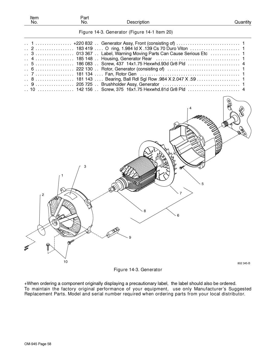
. . | 1 | +220 832 | . . Generator Assy, Front (consisting of) | . . . 1 |
. . | 2 | 183 419 | . . . . O−ring, 1.984 Id X .139 Cs 70 Duro Viton | . . . 1 |
. . | 3 | 013 367 | . . Label, Warning Moving Parts Can Cause Serious Etc | . . . 1 |
. . | 4 | 185 148 | . . Housing, Generator Rear | . . . 1 |
. . | 5 | 186 083 | . . Screw, 437−14x1.75 Hexwhd.93d Gr8 Pld | . . . 4 |
. . | 6 | 222 130 | . . Rotor, Generator (consisting of) | . . . 1 |
. . | 7 | 181 134 | . . . . Fan, Rotor Gen | . . . 1 |
. . | 8 | 181 143 | . . . . Bearing, Ball Rdl Sgl Row .984 X 2.047 X .59 | . . . 1 |
. . | 9 | 205 725 | . . Brushholder Assy, Generator | . . . 1 |
. . 10 | 142 156 | . . Screw, 375−16x1.75 Hexwhd.81d Gr8 Pld | . . . 4 | |
|
|
| 4 |
|
3
1
5
2 | 7 |
| |
| 8 |
| 6 |
| 9 |
10 | 802 |
|
Figure 14-3. Generator
+When ordering a component originally displaying a precautionary label, the label should also be ordered.
To maintain the factory original performance of your equipment, use only Manufacturer’s Suggested Replacement Parts. Model and serial number required when ordering parts from your local distributor.
