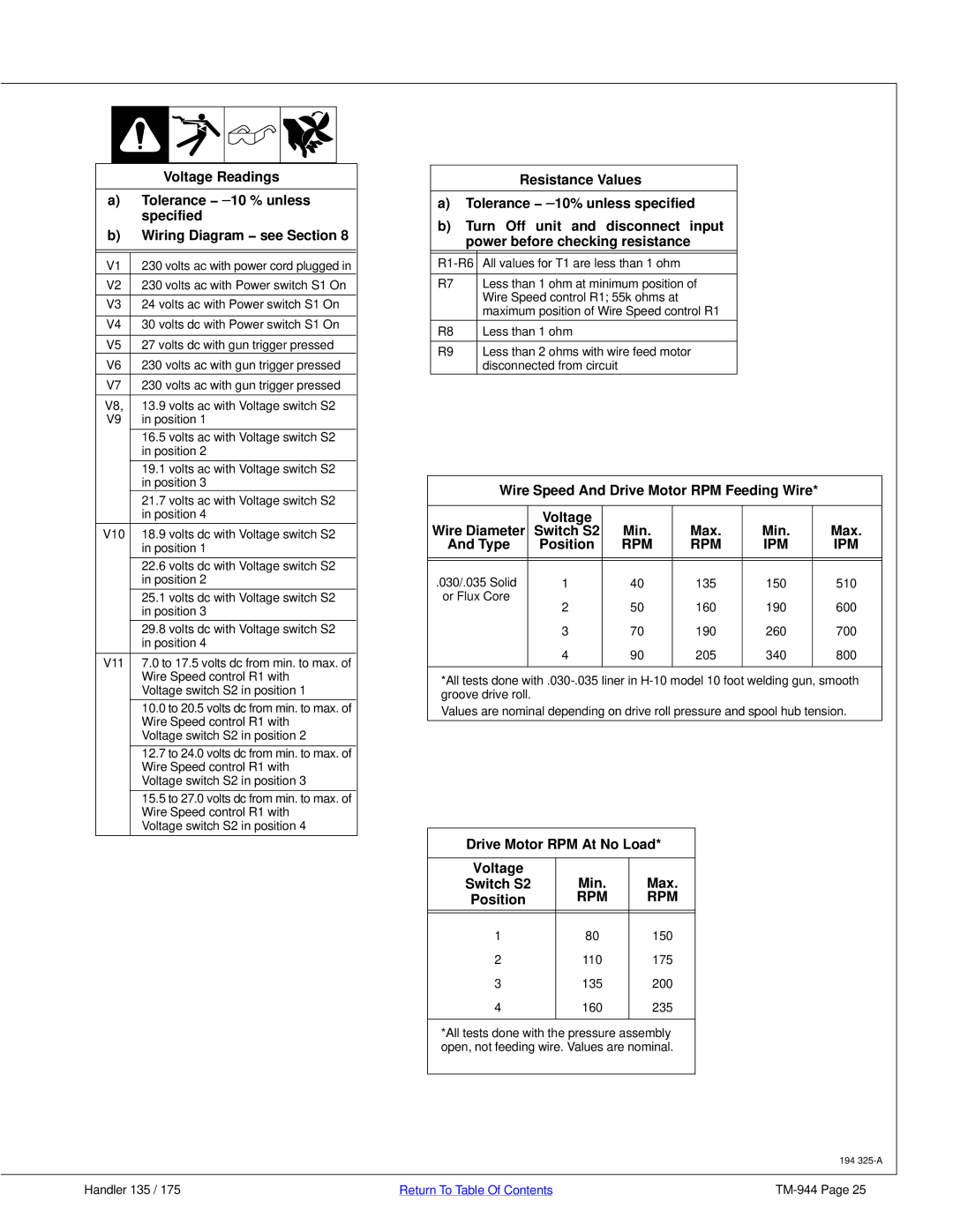
Voltage Readings
a)Tolerance − ±10 % unless specified
b)Wiring Diagram − see Section 8
V1 | 230 volts ac with power cord plugged in |
|
V2 | 230 volts ac with Power switch S1 On | |
|
|
|
V3 | 24 volts ac with Power switch S1 On | |
|
|
|
V4 | 30 volts dc with Power switch S1 On | |
|
|
|
V5 | 27 volts dc with gun trigger pressed | |
V6 | 230 volts ac with gun trigger pressed | |
V7 | 230 volts ac with gun trigger pressed | |
V8, | 13.9 volts ac with Voltage switch S2 | |
V9 | in position 1 | |
| 16.5 volts ac with Voltage switch S2 | |
| in position 2 | |
|
|
|
| 19.1 volts ac with Voltage switch S2 | |
| in position 3 | |
| 21.7 volts ac with Voltage switch S2 | |
| in position 4 | |
V10 | 18.9 volts dc with Voltage switch S2 | |
| in position 1 | |
| 22.6 volts dc with Voltage switch S2 | |
| in position 2 | |
| 25.1 volts dc with Voltage switch S2 | |
| in position 3 | |
| 29.8 volts dc with Voltage switch S2 | |
| in position 4 | |
|
|
|
V11 | 7.0 to 17.5 volts dc from min. to max. of | |
| Wire Speed control R1 with | |
| Voltage switch S2 in position 1 |
|
| 10.0 to 20.5 volts dc from min. to max. of | |
| Wire Speed control R1 with | |
| Voltage switch S2 in position 2 | |
| 12.7 to 24.0 volts dc from min. to max. of | |
| Wire Speed control R1 with | |
| Voltage switch S2 in position 3 | |
| 15.5 to 27.0 volts dc from min. to max. of | |
| Wire Speed control R1 with | |
| Voltage switch S2 in position 4 | |
|
|
|
|
| Resistance Values |
|
| |
a) | Tolerance − ±10% unless specified | |
b) | Turn Off unit and disconnect input | |
| power before checking resistance | |
All values for T1 are less than 1 ohm | ||
|
|
|
R7 |
| Less than 1 ohm at minimum position of |
|
| Wire Speed control R1; 55k ohms at |
|
| maximum position of Wire Speed control R1 |
R8 |
| Less than 1 ohm |
R9 |
| Less than 2 ohms with wire feed motor |
|
| disconnected from circuit |
Wire Speed And Drive Motor RPM Feeding Wire*
| Voltage |
|
|
|
|
Wire Diameter | Switch S2 | Min. | Max. | Min. | Max. |
And Type | Position | RPM | RPM | IPM | IPM |
|
|
|
|
|
|
|
|
|
|
|
|
.030/.035 Solid | 1 | 40 | 135 | 150 | 510 |
or Flux Core | 2 | 50 | 160 | 190 | 600 |
| |||||
| 3 | 70 | 190 | 260 | 700 |
| 4 | 90 | 205 | 340 | 800 |
|
|
|
|
|
|
*All tests done
Values are nominal depending on drive roll pressure and spool hub tension.
Drive Motor RPM At No Load*
Voltage | Min. | Max. |
Switch S2 | ||
Position | RPM | RPM |
|
|
|
|
|
|
1 | 80 | 150 |
2 | 110 | 175 |
3 | 135 | 200 |
4 | 160 | 235 |
|
|
|
*All tests done with the pressure assembly open, not feeding wire. Values are nominal.
194
Handler 135 / 175 | Return To Table Of Contents |