A S S E M B LY
I N S T R U C T I O N S
Step 2f
F R A M E A S S E M B L Y
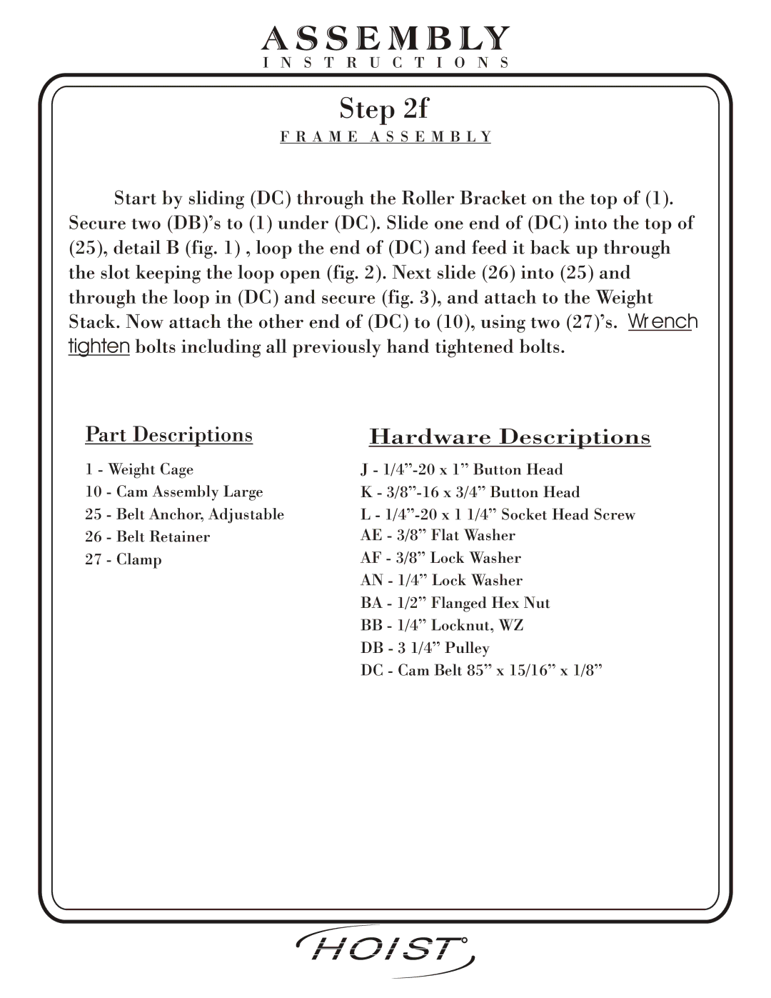
Start by sliding (DC) through the Roller Bracket on the top of (1). Secure two (DB)’s to (1) under (DC). Slide one end of (DC) into the top of (25), detail B (fig. 1) , loop the end of (DC) and feed it back up through the slot keeping the loop open (fig. 2). Next slide (26) into (25) and through the loop in (DC) and secure (fig. 3), and attach to the Weight Stack. Now attach the other end of (DC) to (10), using two (27)’s. Wrench tighten bolts including all previously hand tightened bolts.
Part Descriptions | Hardware Descriptions | |
1 - Weight Cage | J - | |
10 | - Cam Assembly Large | K - |
25 | - Belt Anchor, Adjustable | L - |
26 | - Belt Retainer | AE - 3/8” Flat Washer |
27 | - Clamp | AF - 3/8” Lock Washer |
|
| AN - 1/4” Lock Washer |
|
| BA - 1/2” Flanged Hex Nut |
|
| BB - 1/4” Locknut, WZ |
|
| DB - 3 1/4” Pulley |
|
| DC - Cam Belt 85” x 15/16” x 1/8” |
| HOIST | R | |
Page 17 | 2601 Assembly | ||
FITNESS SYSTEMS |
