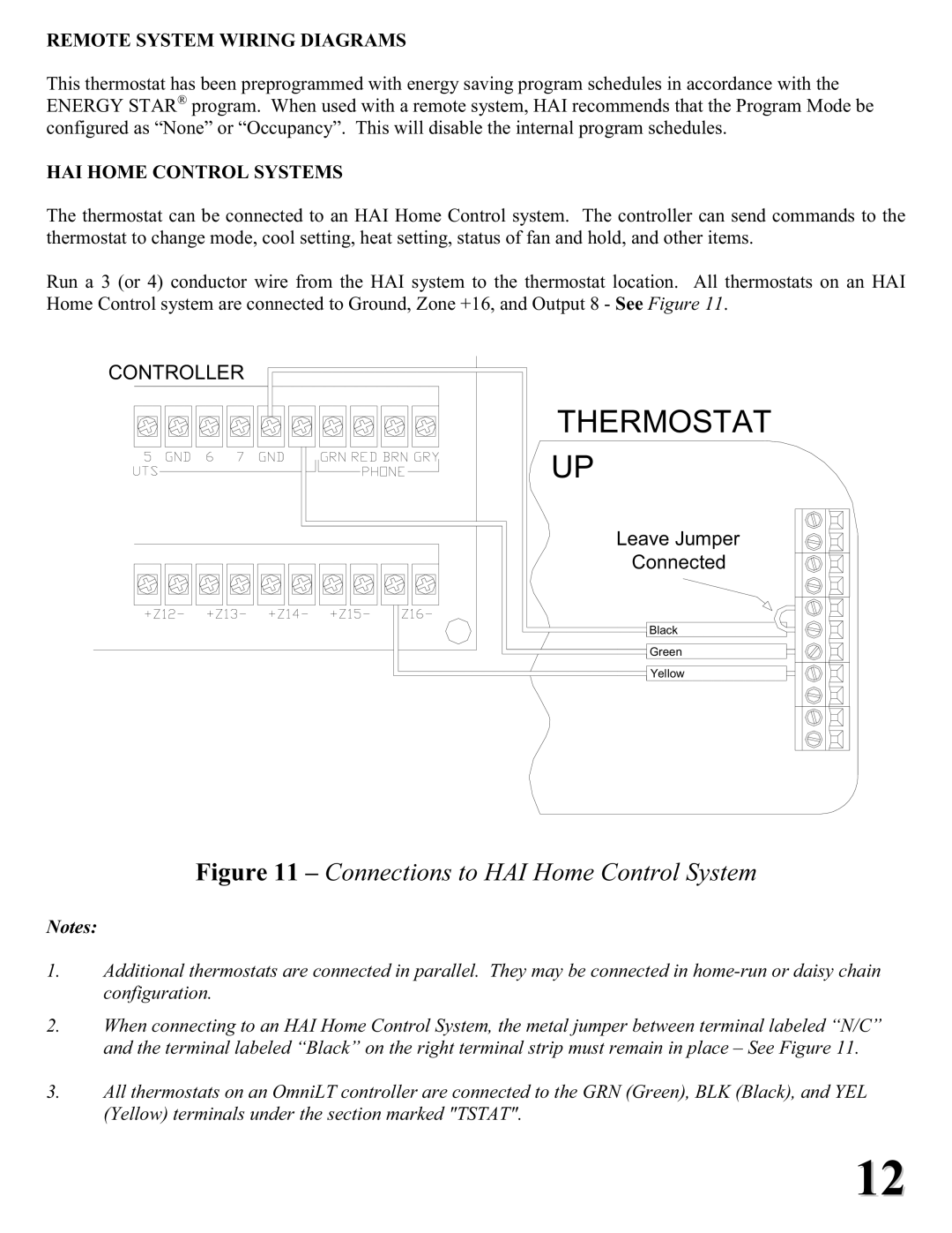
RC-2000 specifications
Home Automation RC-2000: A Smart Revolution in Home ManagementThe Home Automation RC-2000 is an innovative solution designed to bring convenience, security, and efficiency to modern living. This advanced system enables homeowners to seamlessly control a variety of devices within their homes, providing a comprehensive ecosystem that enhances everyday life.
One of the standout features of the RC-2000 is its compatibility with a wide range of smart devices. From lighting and temperature control to security systems and entertainment equipment, the RC-2000 integrates effortlessly with countless devices, allowing users to manage their entire home through a single interface. This compatibility is made possible through its support for multiple communication protocols such as Wi-Fi, Zigbee, Z-Wave, and Bluetooth.
The RC-2000 also excels with its user-friendly mobile app. This intuitive application enables users to monitor and control their home from virtually anywhere, whether inside or outside the house. Customization options within the app allow homeowners to create schedules, set scenes, and automate tasks, making it easy to tailor the system to their unique needs.
Another notable characteristic of the RC-2000 is its advanced security features. Users can set up real-time monitoring and receive alerts for unusual activities in and around their homes. This capability is complemented by integration with smart cameras and locks, ensuring that users can remotely manage their home security with confidence.
The system’s voice control functionality further enhances user experience, as it can be easily integrated with popular virtual assistants like Amazon Alexa, Google Assistant, and Apple HomeKit. This hands-free control allows for seamless interaction with the system, enabling users to adjust settings or command devices through simple voice commands.
Energy efficiency is also a key focus of the RC-2000, as it not only promotes convenience but also aids in reducing energy consumption. Smart thermostats, for instance, can learn user patterns and adjust heating and cooling accordingly, leading to significant savings on energy bills.
With its combination of advanced technologies, comprehensive features, and user-friendly interface, the Home Automation RC-2000 stands at the forefront of smart home solutions. It is designed to provide homeowners with peace of mind, ultimate control, and the enhanced convenience that comes from a truly connected environment. The RC-2000 is not just a gadget; it is a gateway to a smarter, more efficient home.

