MAINTENANCE
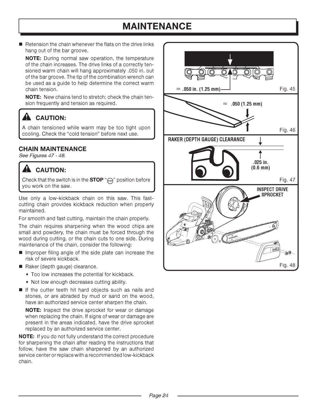
Retension the chain whenever the flats on the drive links hang out of the bar groove.
NOTE: During normal saw operation, the temperature of the chain increases. The drive links of a correctly ten- sioned warm chain will hang approximately .050 in. out of the bar groove. The tip of the combination wrench can be used as a guide to help determine the correct warm chain tension.
NOTE: New chains tend to stretch; check the chain ten- sion frequently and tension as required.
CAUTION: |
|
A chain tensioned while warm may be too tight upon | |
cooling. Check the “cold tension” before next use. | |
CHAIN MAINTENANCE |
|
See Figures 47 - 48. |
|
CAUTION: |
|
Check that the switch is in the STOP “ | ” position before |
you work on the saw. |
|
Use only a | |
cutting chain provides kickback reduction when properly | |
maintained. |
|
For smooth and fast cutting, maintain the chain properly. | |
The chain requires sharpening when the wood chips are | |
small and powdery, the chain must be forced through the | |
wood during cutting, or the chain cuts to one side. During | |
maintenance of the chain, consider the following: | |
�Improper filing angle of the side plate can increase the | |
risk of severe kickback. |
|
Raker (depth gauge) clearance.
•Too low increases the potential for kickback.
•Not low enough decreases cutting ability.
If the cutter teeth hit hard objects such as nails and stones, or are abraded by mud or sand on the wood, have an authorized service center sharpen the chain.
NOTE: Inspect the drive sprocket for wear or damage when replacing the chain. If signs of wear or damage are present in the areas indicated, have the drive sprocket replaced by an authorized service center.
NOTE: If you do not fully understand the correct procedure for sharpening the chain after reading the instructions that follow, have the saw chain sharpened by an authorized service center or replace with a recommended
≈ .050 in. (1.25 mm) | Fig. 45 |
| |
≈ | .050 (1.25 mm) |
Fig. 46
RAKER (DEPTH GAUGE) CLEARANCE
.025 in. (0.6 mm)
Fig. 47
INSPECT DRIVE
SPROCKET
Fig. 48
Page 24
