1100 Series specifications
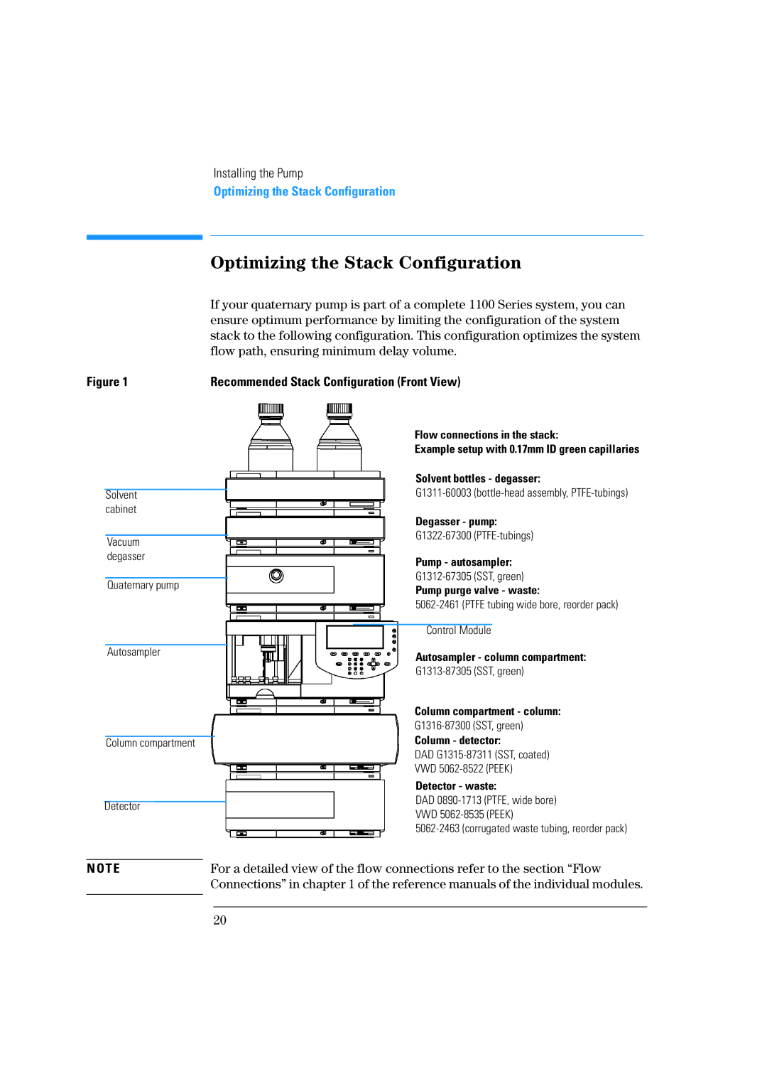
Agilent Technologies 1100 Series is a highly regarded lineup of high-performance liquid chromatography (HPLC) systems designed to meet the demanding needs of laboratories in various fields including pharmaceuticals, environmental testing, and food safety. Known for its versatility, reliability, and advanced technology, the 1100 Series has established itself as a benchmark for analytical performance.One of the standout features of the Agilent 1100 Series is its modular architecture. This design allows users to configure the system according to specific analytical requirements. The components such as pumps, detectors, and autosamplers can be mixed and matched to create a tailored solution, ensuring maximum efficiency and optimal performance. This modularity also facilitates easy upgrades and maintenance, significantly extending the life cycle of the instrument.
At the heart of the 1100 Series is its advanced pumping technology. The system utilizes precise, high-pressure pumps that ensure a consistent flow rate and excellent reproducibility, essential for accurate quantification of analytes. The binary and quaternary pump options provide flexibility in method development, enabling users to perform gradient elution with ease.
The Agilent 1100 Series also boasts a range of detectors, including UV/VIS, fluorescence, and refractive index detectors. Each detector is designed to enhance sensitivity and specificity, enabling the detection of a wide array of compounds. The UV/VIS detector, in particular, is known for its reliable performance and user-friendly interface, which simplifies method setup and data analysis.
Another critical aspect of the 1100 Series is its autosampler. The system's autosamplers provide high throughput and automatic sample handling, which significantly reduces human error and increases productivity. The intelligent design allows for temperature control and reliable sample injection, ensuring optimal results.
In terms of software, the 1100 Series is supported by Agilent’s OpenLAB software, which offers an intuitive platform for method development, data acquisition, and analysis. This software integrates seamlessly with the HPLC hardware, making it easier for scientists to manage workflows and maintain compliance with regulatory requirements.
Overall, the Agilent Technologies 1100 Series represents a significant advancement in liquid chromatography, bringing together ideal characteristics such as modularity, precision, versatility, and sophistication. Its commitment to innovation and quality makes it a preferred choice for laboratories seeking reliable analytical solutions.

