Pilot Burner Flame Check (All models except PGF3, PGX3, and PDX3)
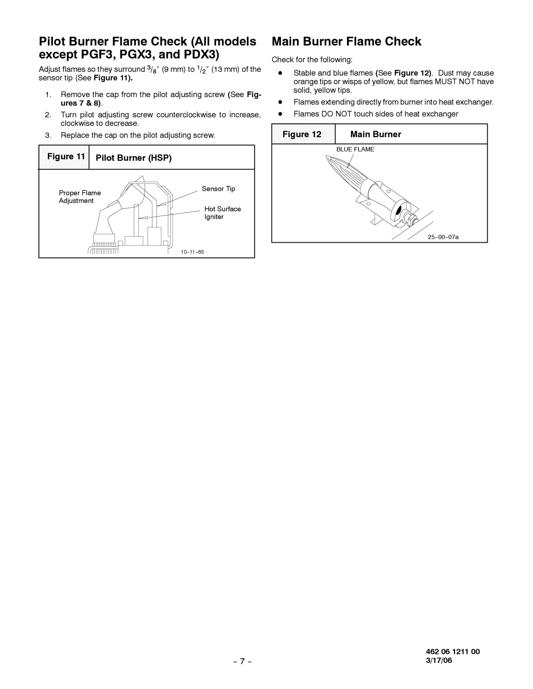
Adjust flames so they surround 3/8″ (9 mm) to 1/2″ (13 mm) of the sensor tip (See Figure 11).
1.Remove the cap from the pilot adjusting screw (See Fig- ures 7 & 8).
2.Turn pilot adjusting screw counterclockwise to increase, clockwise to decrease.
3.Replace the cap on the pilot adjusting screw.
Figure 11 Pilot Burner (HSP)
Proper Flame | Sensor Tip |
| |
Adjustment |
|
| Hot Surface |
| Igniter |
|
Main Burner Flame Check
Check for the following:
DStable and blue flames (See Figure 12). Dust may cause orange tips or wisps of yellow, but flames MUST NOT have solid, yellow tips.
DFlames extending directly from burner into heat exchanger. D Flames DO NOT touch sides of heat exchanger
Figure 12 | Main Burner |
|
|
| BLUE FLAME |
| 462 06 1211 00 |
3/17/06 |
