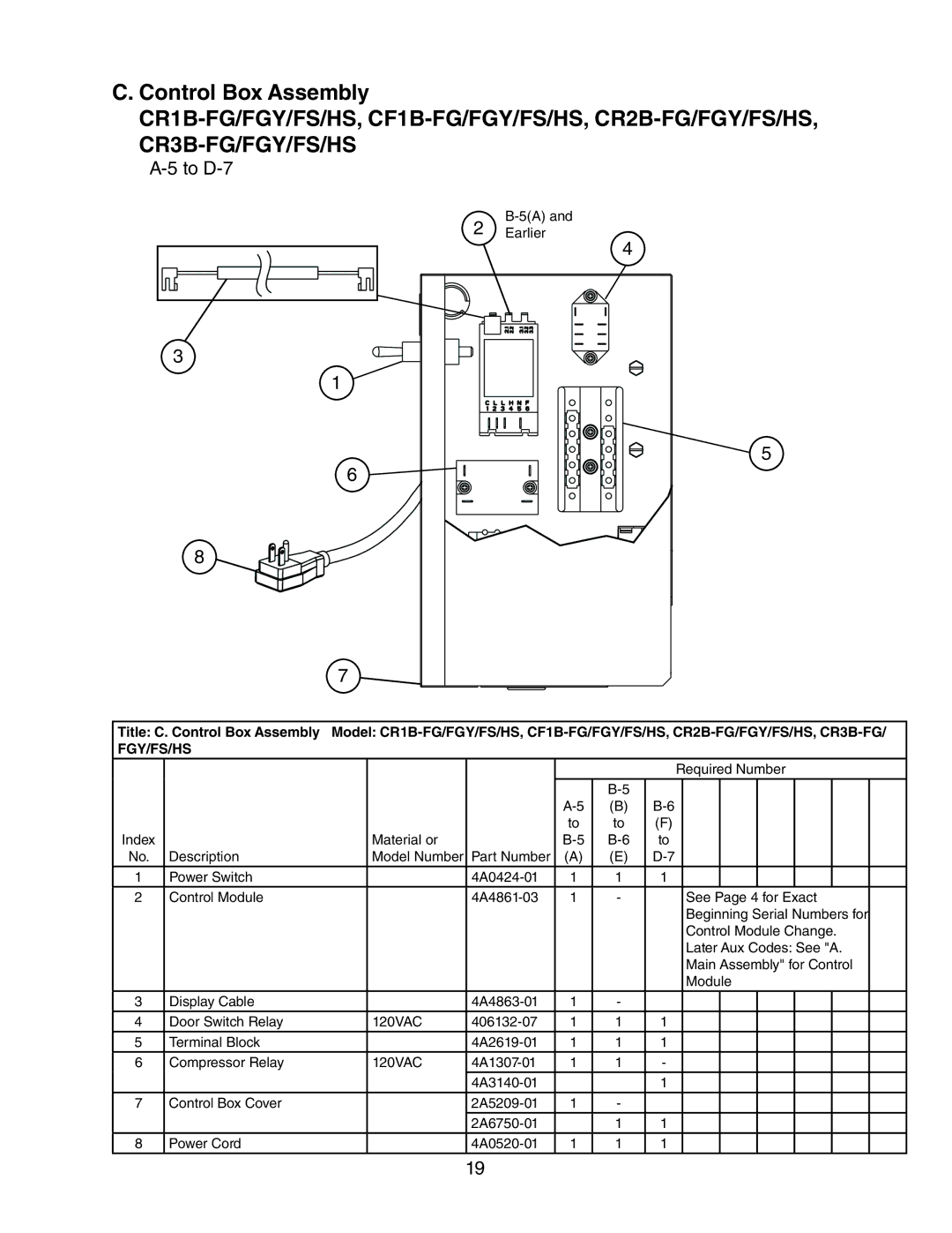
CF1B-FG/FGY/FS/HS. CR2B-FG/FGY/FS/HS, CR2B-FG/FGY/FS/HS, CR1B-FG/FGY/FS/HS, CF3B-FS/HS specifications
The Hoshizaki CR1B, CR2B, and CF series refrigerators, including models like CR1B-FG, CR1B-FGY, CR1B-FS, CR1B-HS, CR2B-FG, CR2B-FGY, CR2B-FS, CR2B-HS, as well as CF1B and CF3B models, are renowned in the food service industry for their durability, efficient cooling technologies, and user-friendly features. These units are primarily designed for commercial applications, ensuring that they meet the rigorous demands of restaurants, cafes, and other food establishments.One of the standout features across these models is the high-efficiency cooling system, which utilizes advanced refrigeration technology. This system is designed to maintain consistent temperatures, ensuring that food items remain fresh and safe for consumption. The units are equipped with an eco-friendly refrigerant that complies with environmental regulations, promoting sustainability while delivering outstanding performance.
Temperature control is another significant characteristic of the Hoshizaki refrigerators. Many models feature digital thermostats that allow for precise temperature adjustments, giving operators complete control over food storage conditions. The easy-to-read LED displays provide real-time monitoring of internal temperatures, reducing the risk of temperature fluctuations that could compromise food safety.
The design of the CR and CF models is another highlight. Built with robust materials, they have stainless steel exteriors that are not only aesthetically pleasing but also easy to clean and resistant to corrosion. The interiors are also constructed for easy maintenance, with smooth surfaces that facilitate the cleaning process.
Additionally, these units often come with adjustable shelving, enabling users to customize the interior space based on their storage needs. Some models also feature energy-saving technologies, helping to reduce electricity costs, which is a crucial aspect for any food service operation.
The noise levels produced by the refrigeration systems in these models are kept to a minimum, ensuring a comfortable work environment for staff.
Overall, the Hoshizaki CR1B, CR2B, and CF series represent a blend of function, performance, and design, making them exceptional choices for any commercial kitchen that requires reliable refrigeration solutions. Their focus on efficiency, user-friendliness, and sustainability aligns with the modern demands of the food service industry, ensuring that operators can maintain food safety and quality while optimizing their operational costs.

