Step 5 – Connect the Motor
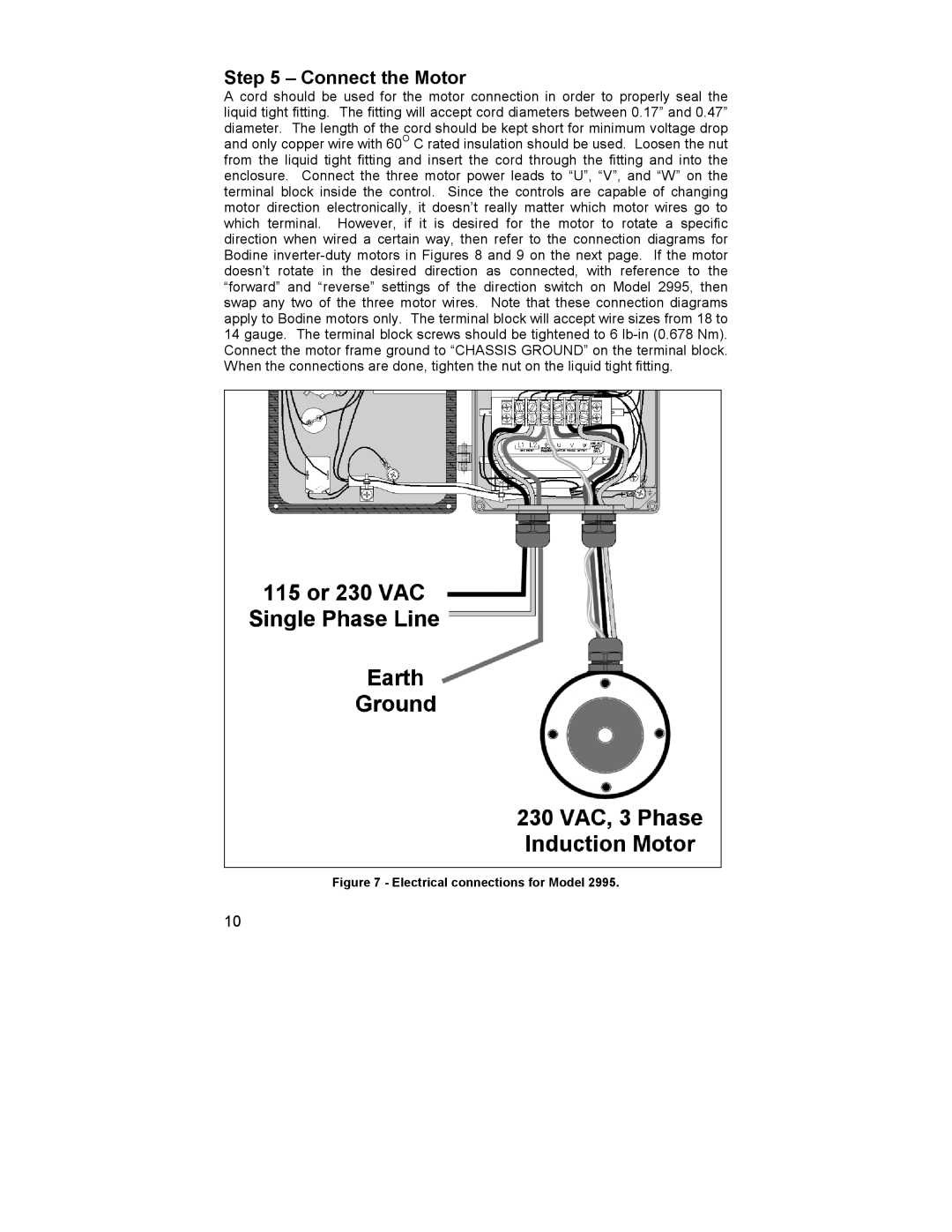
A cord should be used for the motor connection in order to properly seal the liquid tight fitting. The fitting will accept cord diameters between 0.17” and 0.47” diameter. The length of the cord should be kept short for minimum voltage drop and only copper wire with 60O C rated insulation should be used. Loosen the nut from the liquid tight fitting and insert the cord through the fitting and into the enclosure. Connect the three motor power leads to “U”, “V”, and “W” on the terminal block inside the control. Since the controls are capable of changing motor direction electronically, it doesn’t really matter which motor wires go to which terminal. However, if it is desired for the motor to rotate a specific direction when wired a certain way, then refer to the connection diagrams for Bodine
Figure 7 - Electrical connections for Model 2995.
10