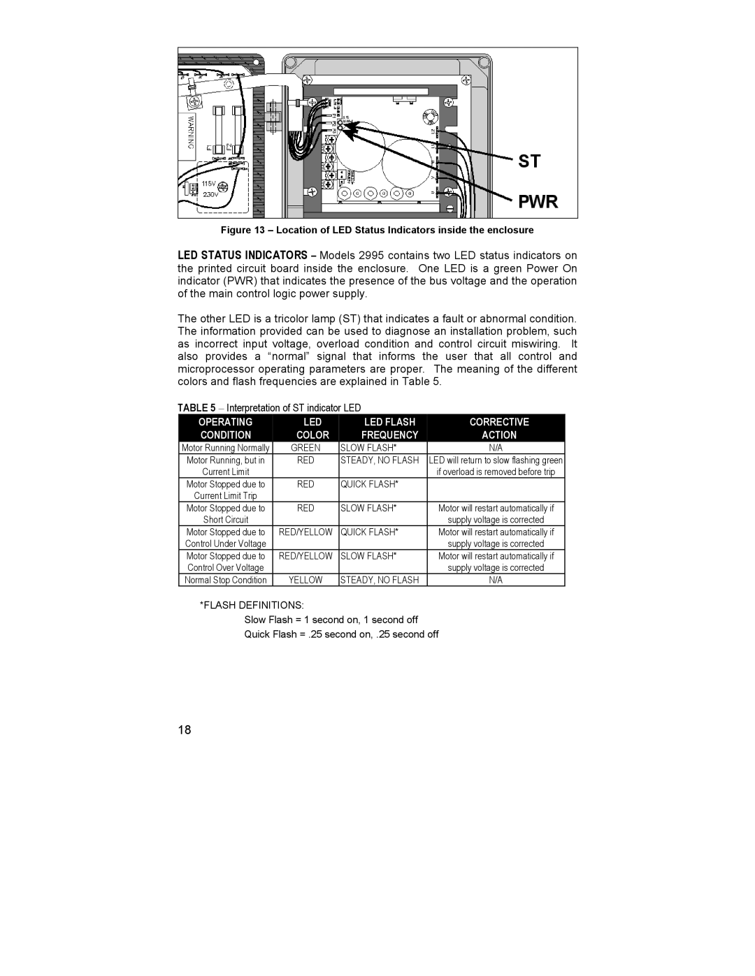
Figure 13 – Location of LED Status Indicators inside the enclosure
LED STATUS INDICATORS – Models 2995 contains two LED status indicators on the printed circuit board inside the enclosure. One LED is a green Power On indicator (PWR) that indicates the presence of the bus voltage and the operation of the main control logic power supply.
The other LED is a tricolor lamp (ST) that indicates a fault or abnormal condition. The information provided can be used to diagnose an installation problem, such as incorrect input voltage, overload condition and control circuit miswiring. It also provides a “normal” signal that informs the user that all control and microprocessor operating parameters are proper. The meaning of the different colors and flash frequencies are explained in Table 5.
TABLE 5 – Interpretation of ST indicator LED |
| ||
OPERATING | LED | LED FLASH | CORRECTIVE |
CONDITION | COLOR | FREQUENCY | ACTION |
Motor Running Normally | GREEN | SLOW FLASH* | N/A |
Motor Running, but in | RED | STEADY, NO FLASH | LED will return to slow flashing green |
Current Limit |
|
| if overload is removed before trip |
Motor Stopped due to | RED | QUICK FLASH* |
|
Current Limit Trip |
|
|
|
Motor Stopped due to | RED | SLOW FLASH* | Motor will restart automatically if |
Short Circuit |
|
| supply voltage is corrected |
Motor Stopped due to | RED/YELLOW | QUICK FLASH* | Motor will restart automatically if |
Control Under Voltage |
|
| supply voltage is corrected |
Motor Stopped due to | RED/YELLOW | SLOW FLASH* | Motor will restart automatically if |
Control Over Voltage |
|
| supply voltage is corrected |
Normal Stop Condition | YELLOW | STEADY, NO FLASH | N/A |
*FLASH DEFINITIONS:
Slow Flash = 1 second on, 1 second off Quick Flash = .25 second on, .25 second off
18