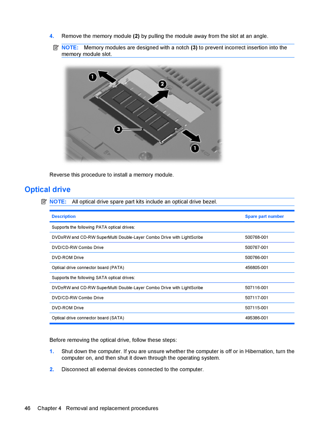
4.Remove the memory module (2) by pulling the module away from the slot at an angle.
![]() NOTE: Memory modules are designed with a notch (3) to prevent incorrect insertion into the memory module slot.
NOTE: Memory modules are designed with a notch (3) to prevent incorrect insertion into the memory module slot.
Reverse this procedure to install a memory module.
Optical drive
![]() NOTE: All optical drive spare part kits include an optical drive bezel.
NOTE: All optical drive spare part kits include an optical drive bezel.
Description | Spare part number |
|
|
Supports the following PATA optical drives: |
|
|
|
DVD±RW and | |
|
|
|
|
|
|
Optical drive connector board (PATA) | |
|
|
Supports the following SATA optical drives: |
|
|
|
DVD±RW and | |
|
|
|
|
|
|
Optical drive connector board (SATA) | |
|
|
Before removing the optical drive, follow these steps:
1.Shut down the computer. If you are unsure whether the computer is off or in Hibernation, turn the computer on, and then shut it down through the operating system.
2.Disconnect all external devices connected to the computer.
46 Chapter 4 Removal and replacement procedures
