Component replacement procedures
This chapter provides removal and replacement procedures.
There are as many as 75 screws that must be removed, replaced, or loosened when servicing the computer. Make special note of each screw size and location during removal and replacement.
Service tag
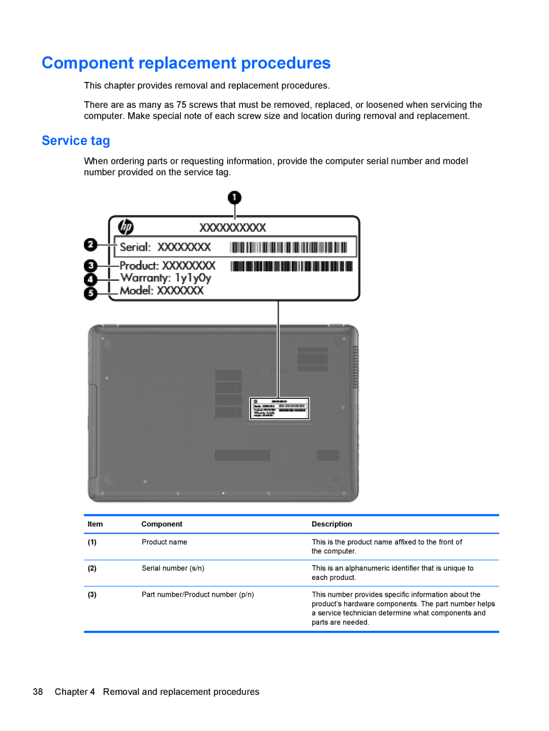
When ordering parts or requesting information, provide the computer serial number and model number provided on the service tag.
Item | Component | Description |
|
|
|
(1) | Product name | This is the product name affixed to the front of |
|
| the computer. |
|
|
|
(2) | Serial number (s/n) | This is an alphanumeric identifier that is unique to |
|
| each product. |
|
|
|
(3) | Part number/Product number (p/n) | This number provides specific information about the |
|
| product’s hardware components. The part number helps |
a service technician determine what components and parts are needed.
38 Chapter 4 Removal and replacement procedures