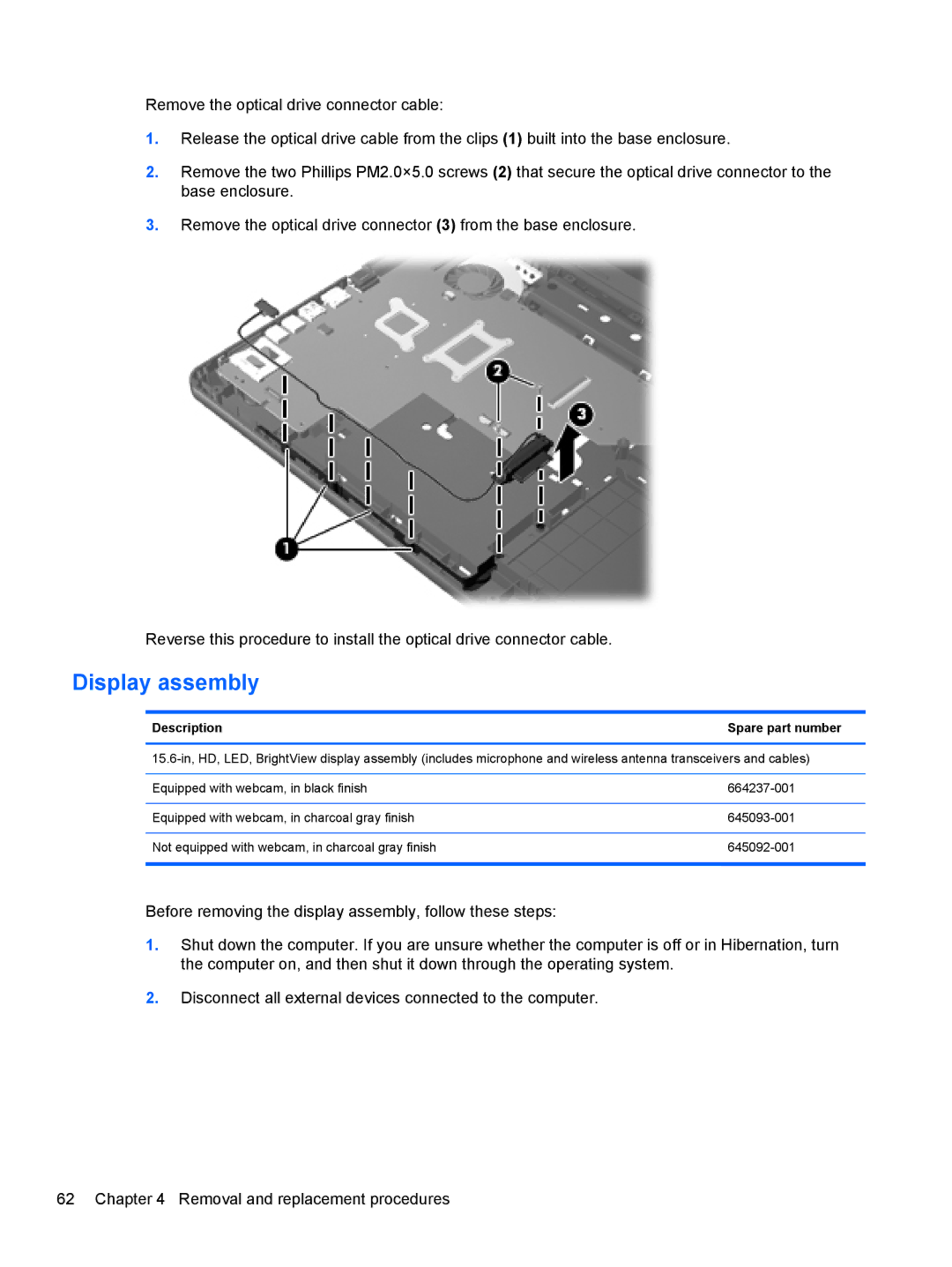
Remove the optical drive connector cable:
1.Release the optical drive cable from the clips (1) built into the base enclosure.
2.Remove the two Phillips PM2.0×5.0 screws (2) that secure the optical drive connector to the base enclosure.
3.Remove the optical drive connector (3) from the base enclosure.
Reverse this procedure to install the optical drive connector cable.
Display assembly
DescriptionSpare part number
Equipped with webcam, in black finish | |
|
|
Equipped with webcam, in charcoal gray finish | |
|
|
Not equipped with webcam, in charcoal gray finish | |
|
|
Before removing the display assembly, follow these steps:
1.Shut down the computer. If you are unsure whether the computer is off or in Hibernation, turn the computer on, and then shut it down through the operating system.
2.Disconnect all external devices connected to the computer.
62 Chapter 4 Removal and replacement procedures