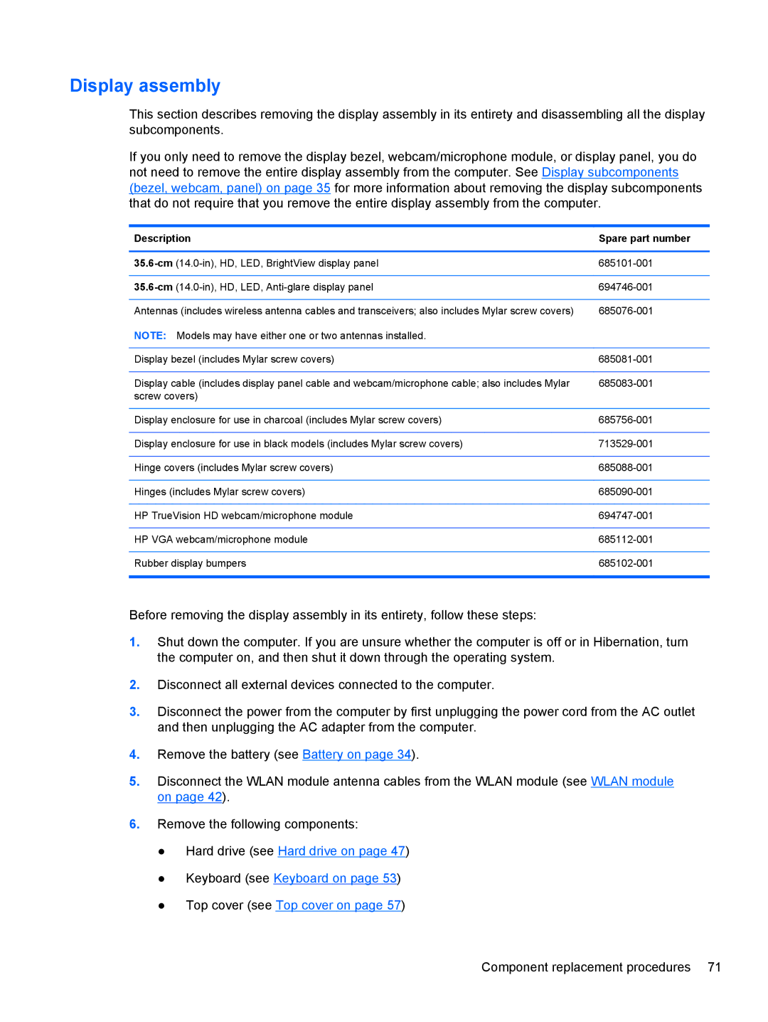
D1E81UA, C2N25UA specifications
HP offers a plethora of laptops catering to various user needs, and the HP C2N25UA and D1E81UA models stand out as compelling options for both personal and professional use. These devices combine powerful performance, modern features, and reliable build quality, making them suitable for diverse computing tasks.The HP C2N25UA, also known as the HP Pavilion series, delivers a vibrant 15.6-inch display that enhances the visual experience with its Full HD resolution. This ensures sharp and clear images, making it ideal for media consumption, whether you’re watching movies, playing games, or working on graphic design projects. With an Intel Core i5 processor at its core, users can expect strong performance in multitasking scenarios, seamlessly switching between applications. Coupled with 8GB of RAM, the C2N25UA accommodates the demands of resource-intensive tasks, ensuring smooth operation and enhanced productivity.
On the other hand, the D1E81UA model falls under the HP Envy line, designed for users who prioritize premium features. It also boasts a high-resolution display but with additional enhancements such as HP’s BrightView technology, which boosts clarity and brightness, making it suitable for outdoor usage. The D1E81UA is equipped with cutting-edge technologies, including a high-performance Intel Core i7 processor and 16GB of RAM, providing ample power for advanced computing tasks like 3D rendering and video editing.
Both models support fast data transfer thanks to their USB Type-C ports, which offer versatile connectivity options. Additionally, they are equipped with high-definition webcams and dual-array microphones, facilitating clear video calls—a necessity in today’s remote work environment. Their lightweight and sleek designs encourage portability, making them easy to carry between home and the office or for travel.
Battery life in both models is commendable, allowing users to work for extended periods without needing to recharge frequently. Additionally, HP includes its fast charge technology, which powers the battery quickly when time is of the essence.
In conclusion, the HP C2N25UA and D1E81UA are robust laptops that blend performance, stylish design, and advanced technology. Whether for professional tasks or everyday use, these models reflect HP’s commitment to quality and innovation, making them worthy contenders in the competitive laptop market.
