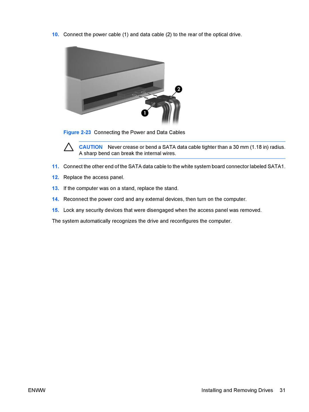
10.Connect the power cable (1) and data cable (2) to the rear of the optical drive.
Figure 2-23 Connecting the Power and Data Cables
CAUTION Never crease or bend a SATA data cable tighter than a 30 mm (1.18 in) radius. A sharp bend can break the internal wires.
11.Connect the other end of the SATA data cable to the white system board connector labeled SATA1.
12.Replace the access panel.
13.If the computer was on a stand, replace the stand.
14.Reconnect the power cord and any external devices, then turn on the computer.
15.Lock any security devices that were disengaged when the access panel was removed.
The system automatically recognizes the drive and reconfigures the computer.
ENWW | Installing and Removing Drives 31 |
