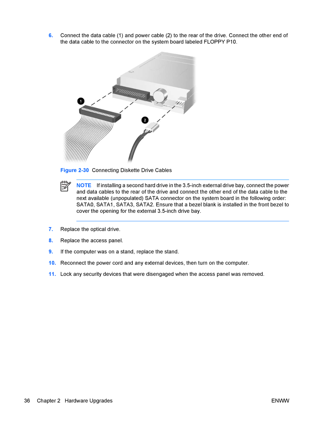
6.Connect the data cable (1) and power cable (2) to the rear of the drive. Connect the other end of the data cable to the connector on the system board labeled FLOPPY P10.
Figure 2-30 Connecting Diskette Drive Cables
NOTE If installing a second hard drive in the
SATA0, SATA1, SATA3, SATA2. Ensure that a bezel blank is installed in the front bezel to cover the opening for the external 3.5-inch drive bay.
7.Replace the optical drive.
8.Replace the access panel.
9.If the computer was on a stand, replace the stand.
10.Reconnect the power cord and any external devices, then turn on the computer.
11.Lock any security devices that were disengaged when the access panel was removed.
36 Chapter 2 Hardware Upgrades | ENWW |