Input/Output Interfaces
5.3PATA Interface
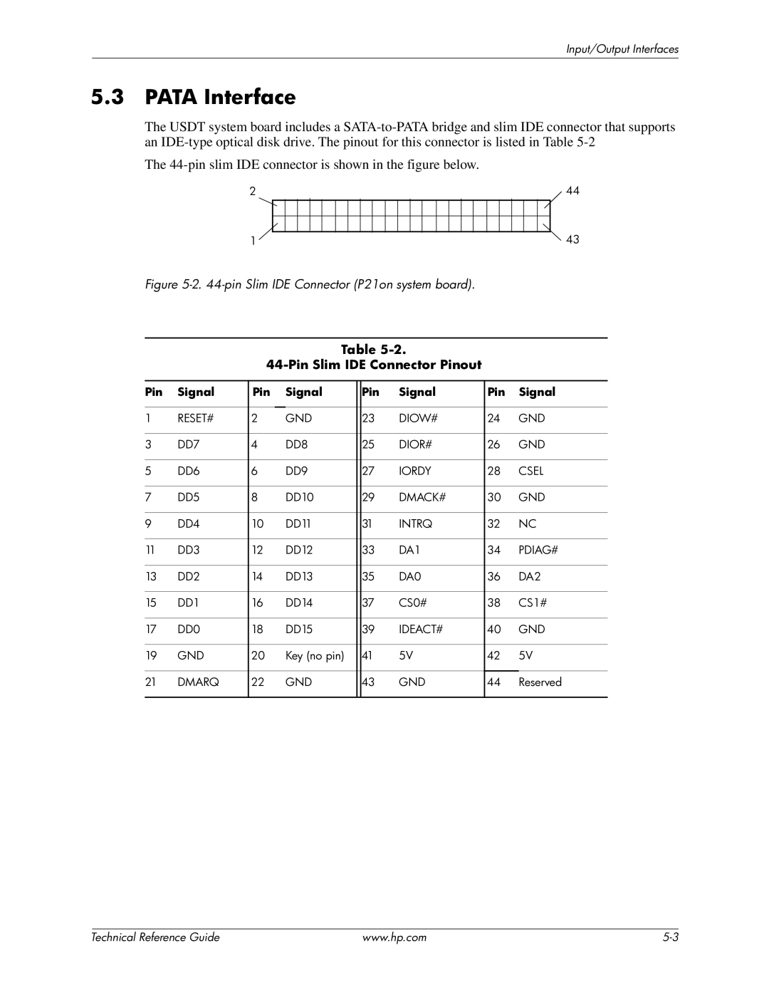
The USDT system board includes a
The
2 | 44 | ||||||||||||||||||||||
1 |
|
|
|
|
|
|
|
|
|
|
|
|
|
|
|
|
|
|
|
|
|
| 43 |
|
|
|
|
|
|
|
|
|
|
|
|
|
|
|
|
|
|
|
|
|
| ||
|
|
|
|
|
|
|
|
|
|
|
|
|
|
|
|
|
|
|
|
|
| ||
Figure 5-2. 44-pin Slim IDE Connector (P21on system board).
Table
44-Pin Slim IDE Connector Pinout
Pin | Signal | Pin | Signal |
| Pin | Signal | Pin | Signal |
|
|
|
|
|
|
|
|
|
1 | RESET# | 2 | GND |
| 23 | DIOW# | 24 | GND |
|
|
|
|
|
|
|
|
|
3 | DD7 | 4 | DD8 |
| 25 | DIOR# | 26 | GND |
|
|
|
|
|
|
|
|
|
5 | DD6 | 6 | DD9 |
| 27 | IORDY | 28 | CSEL |
|
|
|
|
|
|
|
|
|
7 | DD5 | 8 | DD10 |
| 29 | DMACK# | 30 | GND |
|
|
|
|
|
|
|
|
|
9 | DD4 | 10 | DD11 |
| 31 | INTRQ | 32 | NC |
|
|
|
|
|
|
|
|
|
11 | DD3 | 12 | DD12 |
| 33 | DA1 | 34 | PDIAG# |
|
|
|
|
|
|
|
|
|
13 | DD2 | 14 | DD13 |
| 35 | DA0 | 36 | DA2 |
|
|
|
|
|
|
|
|
|
15 | DD1 | 16 | DD14 |
| 37 | CS0# | 38 | CS1# |
|
|
|
|
|
|
|
|
|
17 | DD0 | 18 | DD15 |
| 39 | IDEACT# | 40 | GND |
|
|
|
|
|
|
|
|
|
19 | GND | 20 | Key (no pin) |
| 41 | 5V | 42 | 5V |
|
|
|
|
|
|
|
|
|
21 | DMARQ | 22 | GND |
| 43 | GND | 44 | Reserved |
|
|
|
|
|
|
|
|
|
| Technical Reference Guide | www.hp.com |
