Power and Signal Distribution
Table
System Board Component Designations
SW50 | Clear CMOS switch |
|
XMM1 | Memory slot (black) |
|
XMM2 | Memory slot (white) |
|
XMM3 | Memory slot (white) | SFF & CMT only |
XMM4 | Memory slot (white) | SFF & CMT only |
XU1 | Processor socket |
|
XB2 | Battery socket |
|
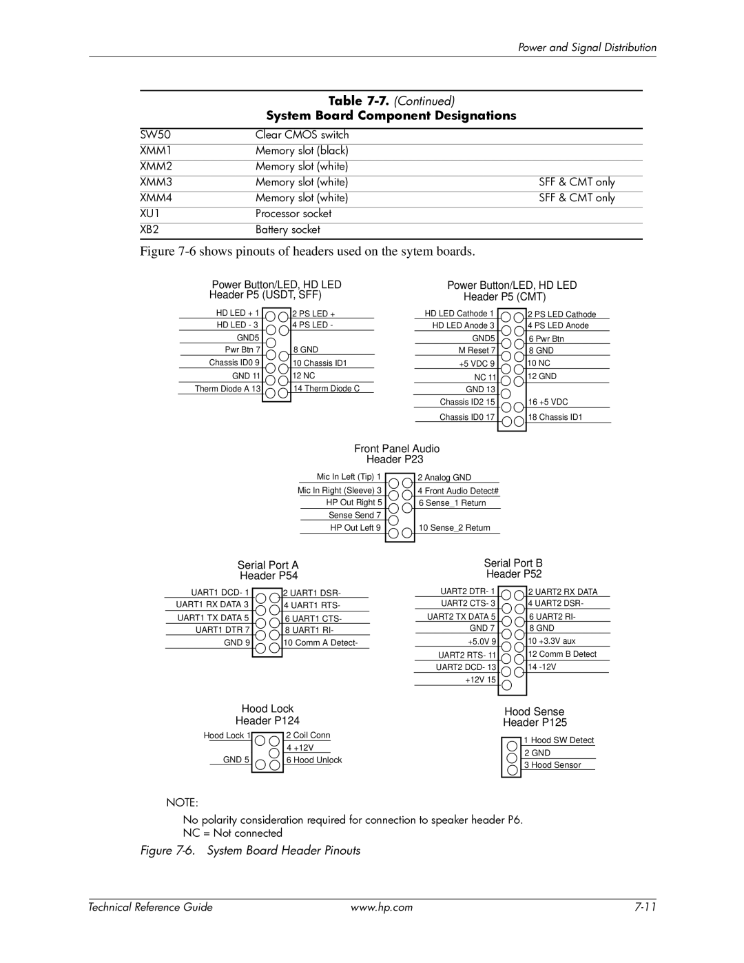
Figure 7-6 shows pinouts of headers used on the sytem boards.
Power Button/LED, HD LED | Power Button/LED, HD LED |
Header P5 (USDT, SFF) | Header P5 (CMT) |
HD LED + 1
HD LED - 3
GND5
Pwr Btn 7
Chassis ID0 9
GND 11
Therm Diode A 13
2 PS LED +
4 PS LED -
8 GND
10 Chassis ID1
12 NC
14 Therm Diode C
HD LED Cathode 1
HD LED Anode 3
GND5
M Reset 7
+5 VDC 9
NC 11
GND 13
Chassis ID2 15
Chassis ID0 17
2 PS LED Cathode
4 PS LED Anode
6 Pwr Btn
8GND 10 NC 12 GND
16 +5 VDC
18 Chassis ID1
Front Panel Audio
Header P23
Mic In Left (Tip) 1
Mic In Right (Sleeve) 3 HP Out Right 5
Sense Send 7
HP Out Left 9
2 Analog GND
4 Front Audio Detect#
6 Sense_1 Return
10 Sense_2 Return
Serial Port A | Serial Port B |
Header P54 | Header P52 |
UART1 DCD- 1
UART1 RX DATA 3
UART1 TX DATA 5
UART1 DTR 7
GND 9
2UART1 DSR-
4 UART1 RTS-
6 UART1 CTS-
8 UART1 RI-
10 Comm A Detect-
UART2 DTR- 1
UART2 CTS- 3
UART2 TX DATA 5
GND 7
+5.0V 9
UART2 RTS- 11
UART2 DCD- 13
+12V 15
2 UART2 RX DATA
4 UART2 DSR-
6UART2 RI-
8GND
10 +3.3V aux
12 Comm B Detect
14
Hood Lock
Header P124
Hood Lock 1 |
| 2 Coil Conn | ||
| ||||
|
|
| 4 +12V |
|
| GND 5 |
| 6 Hood Unlock | |
|
|
|
|
|
Hood Sense
Header P125
1 Hood SW Detect
2GND
3Hood Sensor
NOTE:
No polarity consideration required for connection to speaker header P6.
NC = Not connected
Figure 7-6. System Board Header Pinouts
| Technical Reference Guide | www.hp.com |