Integrated Graphics Subsystem
6.5.2 Digital Monitor Connector
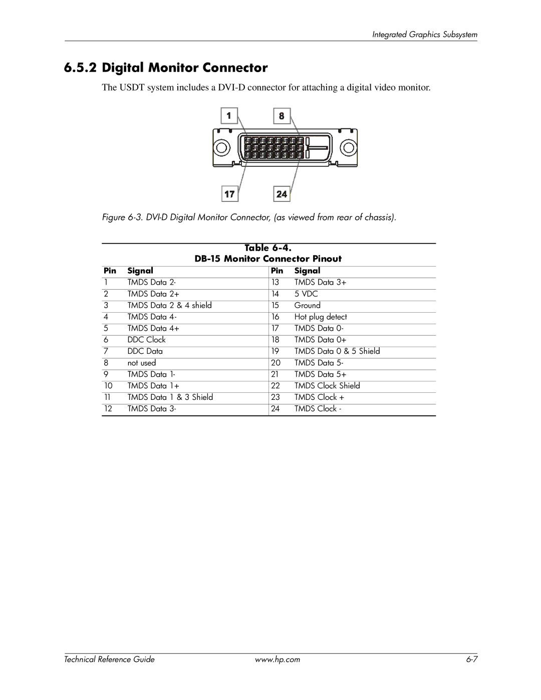
The USDT system includes a
Figure 6-3. DVI-D Digital Monitor Connector, (as viewed from rear of chassis).
Table
DB-15 Monitor Connector Pinout
Pin | Signal | Pin | Signal |
1 | TMDS Data 2- | 13 | TMDS Data 3+ |
2 | TMDS Data 2+ | 14 | 5 VDC |
3 | TMDS Data 2 & 4 shield | 15 | Ground |
4 | TMDS Data 4- | 16 | Hot plug detect |
5 | TMDS Data 4+ | 17 | TMDS Data 0- |
6 | DDC Clock | 18 | TMDS Data 0+ |
7 | DDC Data | 19 | TMDS Data 0 & 5 Shield |
8 | not used | 20 | TMDS Data 5- |
9 | TMDS Data 1- | 21 | TMDS Data 5+ |
10 | TMDS Data 1+ | 22 | TMDS Clock Shield |
11 | TMDS Data 1 & 3 Shield | 23 | TMDS Clock + |
12 | TMDS Data 3- | 24 | TMDS Clock - |
| Technical Reference Guide | www.hp.com |