10.If the system configuration includes only one optical drive, connect the SATA data cable to the white system board connector labeled SATA1 . If you are adding a second optical drive, connect the SATA data cable to the orange system board connector labeled SATA3.
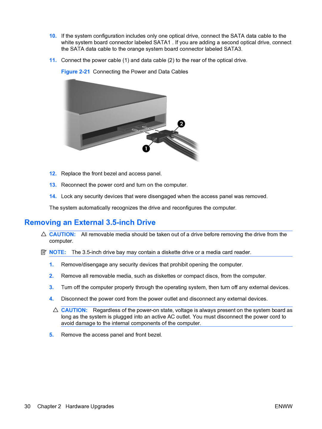
11.Connect the power cable (1) and data cable (2) to the rear of the optical drive. Figure
12.Replace the front bezel and access panel.
13.Reconnect the power cord and turn on the computer.
14.Lock any security devices that were disengaged when the access panel was removed. The system automatically recognizes the drive and reconfigures the computer.
Removing an External 3.5-inch Drive
![]() CAUTION: All removable media should be taken out of a drive before removing the drive from the computer.
CAUTION: All removable media should be taken out of a drive before removing the drive from the computer.
![]() NOTE: The
NOTE: The
1.Remove/disengage any security devices that prohibit opening the computer.
2.Remove all removable media, such as diskettes or compact discs, from the computer.
3.Turn off the computer properly through the operating system, then turn off any external devices.
4.Disconnect the power cord from the power outlet and disconnect any external devices.
![]() CAUTION: Regardless of the
CAUTION: Regardless of the
5.Remove the access panel and front bezel.
30 Chapter 2 Hardware Upgrades | ENWW |
