6.Remove the optical drive (see Optical drive on page 34).
7.Remove the hard drive (see Hard drive on page 36)
8.Remove the keyboard (see Keyboard on page 44).
9.Remove the top cover (see Top cover on page 48).
When replacing the system board, be sure that the following components are removed from the defective system board and installed on the replacement system board:
●Memory module (see Memory module on page 39)
●RTC battery (see RTC battery on page 69)
●Fan and heat sink (see Fan and heat sink on page 70)
●PCH heat sink (see PCH heat sink on page 73)
●Processor (see Processor on page 74)
Remove the system board:
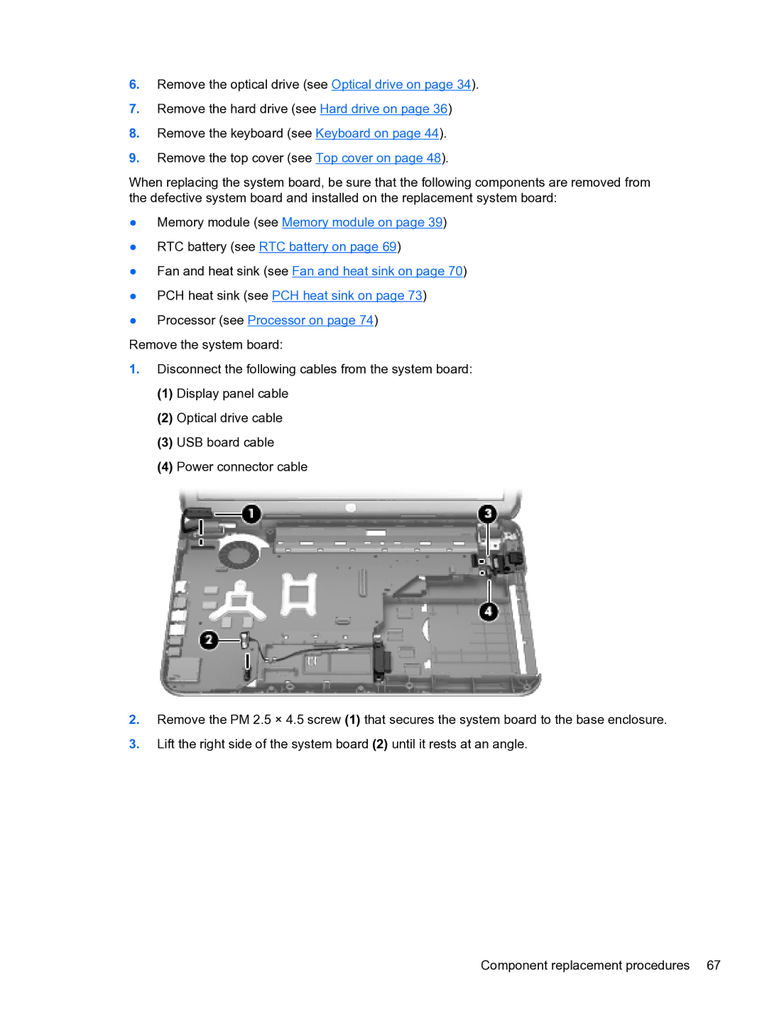
1.Disconnect the following cables from the system board:
(1)Display panel cable
(2)Optical drive cable
(3)USB board cable
(4)Power connector cable
2.Remove the PM 2.5 × 4.5 screw (1) that secures the system board to the base enclosure.
3.Lift the right side of the system board (2) until it rests at an angle.
Component replacement procedures 67